

CCNA_R&S-Student_Lab_Manual
.pdfWhat is the Service Set Identifier (SSID) for the wireless router of your connection?
________________________________________________________________
What is the speed of your wireless connection? __________________________
d. Click Details to display the Network Connection Details window.
© 2013 Cisco and/or its affiliates. All rights reserved. This document is Cisco Public. Page 71 of 257
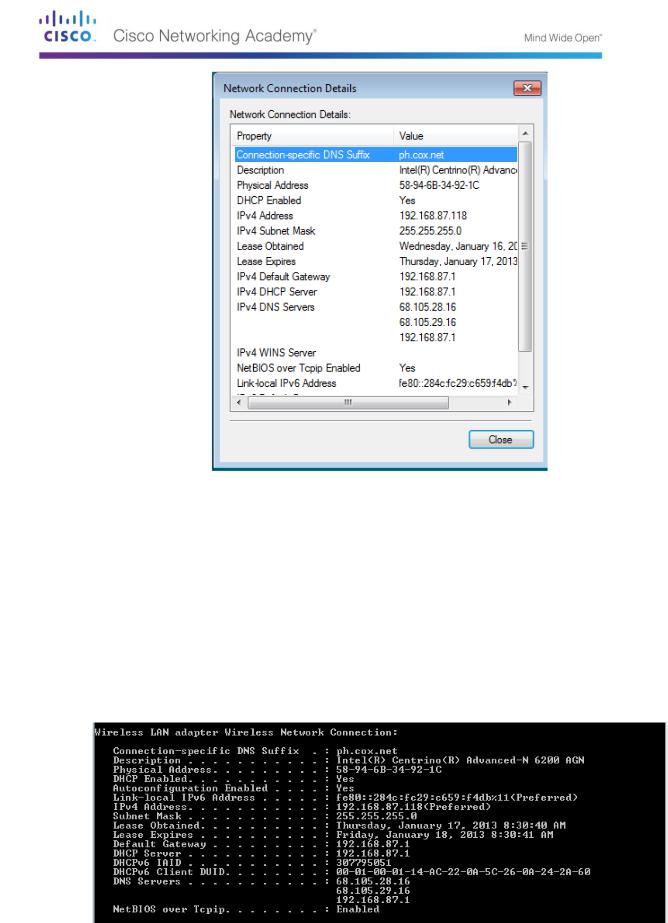
What is the MAC address of your wireless NIC?
_____________________________________________
Do you have multiple IPv4 DNS Servers listed?
______________________________________________
Why would multiple DNS Servers be listed?
__________________________________________________________________________
__________
__________________________________________________________________________
__________
e.When you have reviewed the network connection details, click Close.
f.Open a command window prompt and type ipconfig /all.
Notice that the information displayed here is the same information that was displayed in the Network Connection Details window in Step d.
© 2013 Cisco and/or its affiliates. All rights reserved. This document is Cisco Public. Page 72 of 257
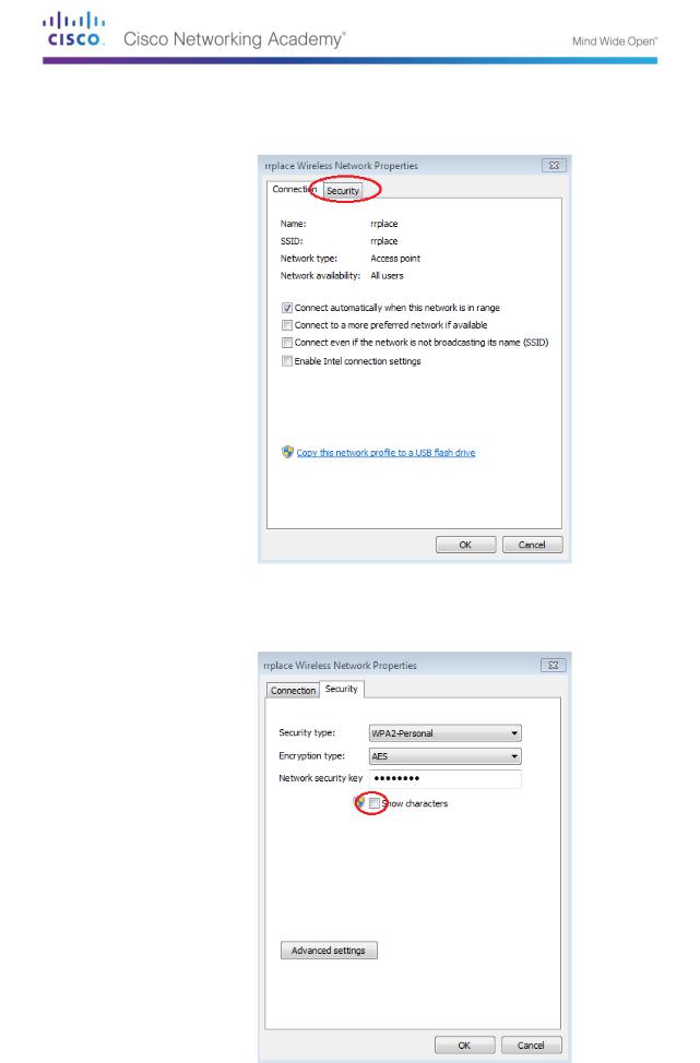
g.Close the command window and the Network Connection Details windows. This should bring you back to the Wireless Network Connection Status window. Click Wireless Properties.
h.In the Wireless Network Properties window, click the Security tab.
i.The type of security the connected wireless router has implemented displays. Click the Show characters check box to display the actual Network security key, instead of the hidden characters, and then click OK.
© 2013 Cisco and/or its affiliates. All rights reserved. This document is Cisco Public. Page 73 of 257
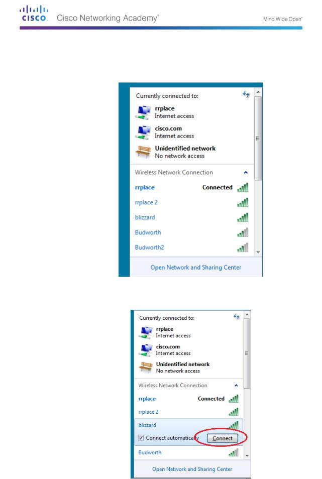
j.Close the Wireless Network Properties and the Network Connection Status windows. Select and right-click the Wireless Network Connection option > Connect/Disconnect. A pop-up window should appear at the bottom right corner of your desktop that displays your current connections, along with a list of SSIDs that are in range of the wireless NIC of your PC. If a scrollbar appears on the right side of this window, you can use it to display additional SSIDs.
k.To join one of the other wireless network SSIDs listed, click the SSID that you want to join, and then click Connect.
© 2013 Cisco and/or its affiliates. All rights reserved. This document is Cisco Public. Page 74 of 257
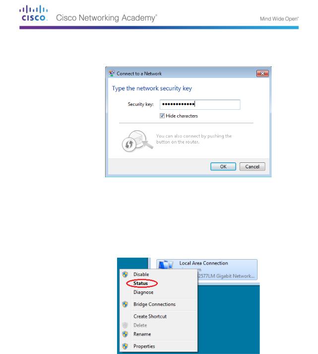
l.If you have selected a secure SSID, you are prompted to enter the Security key for the SSID. Type the security key for that SSID and click OK. You can click the Hide characters check box to prevent people from seeing what you type in the Security key field.
Step 3: Work with your wired NIC.
a.On the Network Connections window, select and right-click the Local Area Connection option to display the drop-down list. If the NIC is disabled, enable it, and then click the Status option.
Note: You must have an Ethernet cable attaching your PC NIC to a switch or similar device to see the status. Many wireless routers have a small 4-port Ethernet switch built-in. You can connect to one of the ports using a straight-through Ethernet patch cable.
b.The Local Area Connection Status window will open. This window displays information about your wired connection to the LAN.
© 2013 Cisco and/or its affiliates. All rights reserved. This document is Cisco Public. Page 75 of 257
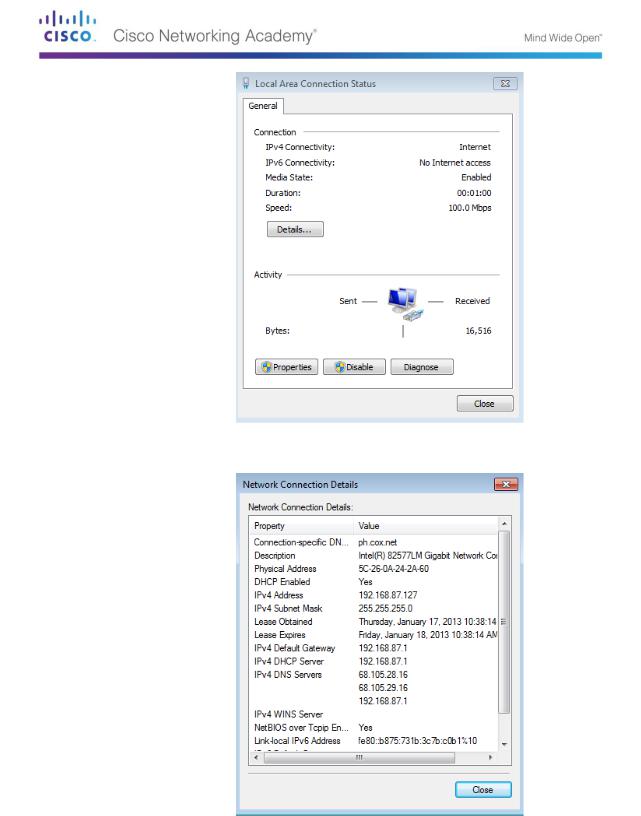
Click Details… to view the address information for your LAN connection.
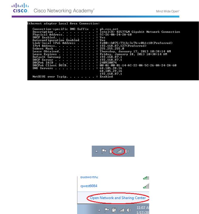
c.Open a command window prompt and type ipconfig /all. Find your Local Area Connection information and compare this with the information displayed in the Network Connection Details window.
©2013 Cisco and/or its affiliates. All rights reserved. This document is Cisco Public.
Page 76 of 257
d. Close all windows on your desktop.
Part 27: Identify and Use the System Tray Network Icons
In Part 2, you will use the network icons in your system tray to determine and control the NICs on your PC.
Step 1: Use the Wireless Network icon.
a.Click the system tray Wireless Network icon to view the pop-up window that displays the SSIDs that are in-range of your wireless NIC. When the system tray displays the Wireless Network icon, the wireless NIC is active.
b.Click the Open Network and Sharing Center link. Note: This is a shortcut way to bring up this window.
c.In the left pane, click the Change adapter settings link to display the Network Connections window.
d.Select and right-click the Wireless Network Connection, and then click Disable to disable your wireless NIC.
© 2013 Cisco and/or its affiliates. All rights reserved. This document is Cisco Public. Page 77 of 257
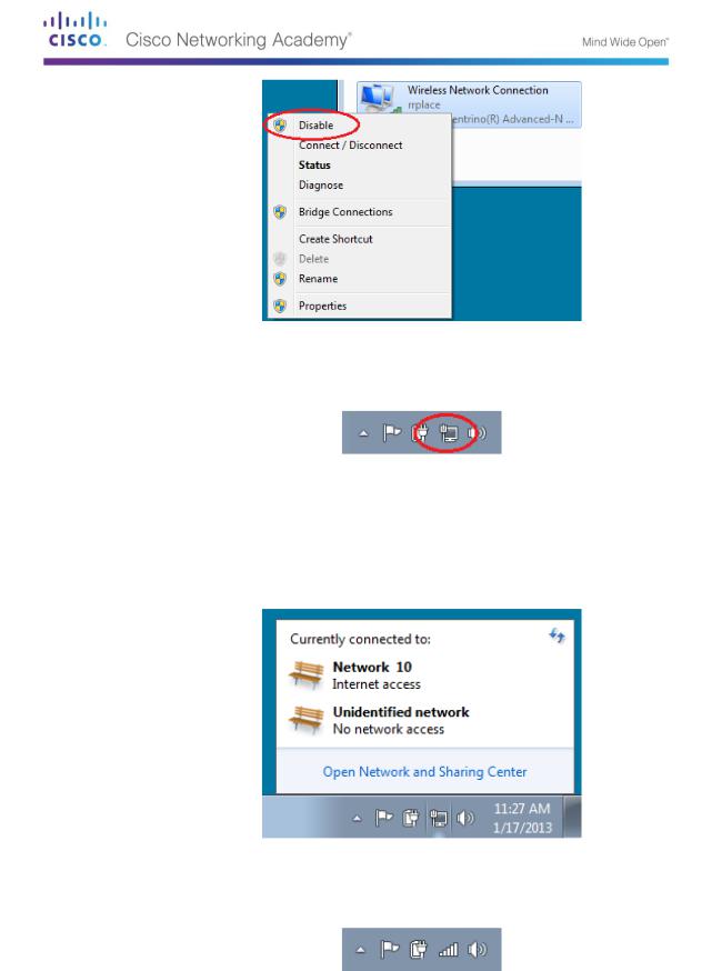
e.Examine your system tray. The Wireless Network Connection icon should be replaced by the Wired Network icon, which indicates that you are using your wired NIC for network connectivity.
Note: If both NICs are active, the Wireless Network icon is the one that is displayed.
Step 2: Use the Wired Network icon.
a.Click the Wired Network icon. Notice that the Wireless SSIDs are no longer displayed in this pop-up window, but you still have the ability to get to the Network and Sharing Center window from here.
b.Click the Open Network and Sharing Center link > Change adapter settings and Enable your Wireless Network Connection. The Wireless Network icon should replace the Wired Network icon in your system tray.
Step 3: Identify the Network Problem icon.
a.On the Network Connections window, disable both the Wireless Network Connection and the Local Area Connection.
©2013 Cisco and/or its affiliates. All rights reserved. This document is Cisco Public.
Page 78 of 257
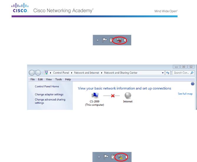
b.The system tray now displays the Network Disabled icon, which indicates that network connectivity has been disabled.
c.You can click this icon to return to the Network and Sharing Center window (examine the network diagram at the top).
You can click the red X to have the PC troubleshoot the problem with the network connection. Troubleshooting attempts to resolve the network issue for you.
d.If troubleshooting did not enable one of your NICs, then you should do this manually to restore the network connectivity of your PC.
Note: If a network adapter is enabled and the NIC is unable to establish network connectivity, then the Network Problem icon appears in the system tray.
If this icon appears, you can troubleshoot this issue just like you did in Step 3c.
Reflection
Why would you activate more than one NIC on a PC?
_____________________________________________________________________________
__________
_____________________________________________________________________________
__________
© 2013 Cisco and/or its affiliates. All rights reserved. This document is Cisco Public. Page 79 of 257
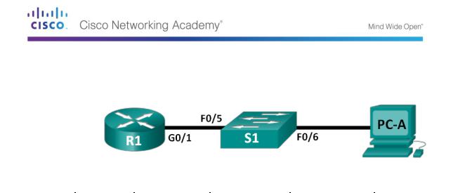
Lab 9 – Viewing Network Device MAC Addresses
Topology
Addressing Table
Device |
Interface |
IP Address |
Subnet Mask |
Default Gateway |
|
|
|
|
|
R1 |
G0/1 |
192.168.1.1 |
255.255.255.0 |
N/A |
|
|
|
|
|
S1 |
VLAN 1 |
N/A |
N/A |
N/A |
|
|
|
|
|
PC-A |
NIC |
192.168.1.3 |
255.255.255.0 |
192.168.1.1 |
|
|
|
|
|
Objectives
Part 1: Set Up the Topology and Initialize Devices
Set up equipment to match the network topology.
Initialize and restart (if necessary) the router and switch.
Part 2: Configure Devices and Verify Connectivity
Assign static IP address to PC-A NIC.
Configure basic information on R1.
Assign a static IP address to R1.
Verify network connectivity.
Part 3: Display, Describe, and Analyze Ethernet MAC Addresses
Analyze MAC address for PC-A.
Analyze MAC addresses for router R1.
Display the MAC address table on switch S1.
Background / Scenario
Every device on an Ethernet LAN is identified by a Layer-2 MAC address. This address is burned into the NIC. This lab will explore and analyze the components that make up a MAC address, and how you can find this information on various networking devices, such as a router, switch, and PC.
You will cable the equipment as shown in the topology. You will then configure the router and PC to match the addressing table. You will verify your configurations by testing for network connectivity.
After the devices have been configured and network connectivity has been verified, you will use various commands to retrieve information from the devices to answer questions about your network equipment.
Note: The routers used with CCNA hands-on labs are Cisco 1941 Integrated Services Routers (ISRs) with Cisco IOS Release 15.2(4)M3 (universalk9 image). The switches used are Cisco Catalyst 2960s with Cisco IOS Release 15.0(2) (lanbasek9 image). Other routers, switches, and Cisco IOS versions can be used. Depending on the model and Cisco IOS version, the commands
© 2013 Cisco and/or its affiliates. All rights reserved. This document is Cisco Public. Page 80 of 257