

CCNA_R&S-Student_Lab_Manual
.pdfStep 9: Examine the captured data.
In Step 3, examine the data that was generated by the ping requests of your team member’s PC.
Wireshark data is displayed in three sections: 1) The top section displays the list of PDU frames captured with a summary of the IP packet information listed, 2) the middle section lists PDU information for the frame selected in the top part of the screen and separates a captured PDU frame by its protocol layers, and 3) the bottom section displays the raw data of each layer. The raw data is displayed in both hexadecimal and decimal form.
Click the first ICMP request PDU frames in the top section of Wireshark. Notice that the Source column has your PC’s IP address, and the Destination contains the IP address of the teammate’s PC you pinged.
© 2013 Cisco and/or its affiliates. All rights reserved. This document is Cisco Public. Page 51 of 257
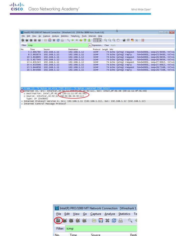
With this PDU frame still selected in the top section, navigate to the middle section. Click the plus sign to the left of the Ethernet II row to view the Destination and Source MAC addresses.
Does the Source MAC address match your PC’s interface? ______
Does the Destination MAC address in Wireshark match the MAC address that of your team member’s?
_____
How is the MAC address of the pinged PC obtained by your PC?
__________________________________________________________________________
_________
Note: In the preceding example of a captured ICMP request, ICMP data is encapsulated inside an IPv4 packet PDU (IPv4 header) which is then encapsulated in an Ethernet II frame PDU (Ethernet II header) for transmission on the LAN.
Part 6: Capture and Analyze Remote ICMP Data in Wireshark
In Part 3, you will ping remote hosts (hosts not on the LAN) and examine the generated data from those pings. You will then determine what is different about this data from the data examined in Part 2.
Step 10: Start capturing data on interface.
Click the Interface List icon to bring up the list PC interfaces again.
© 2013 Cisco and/or its affiliates. All rights reserved. This document is Cisco Public. Page 52 of 257
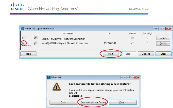
Make sure the check box next to the LAN interface is checked, and then click Start.
A window prompts to save the previously captured data before starting another capture. It is not necessary to save this data. Click Continue without Saving.
© 2013 Cisco and/or its affiliates. All rights reserved. This document is Cisco Public. Page 53 of 257
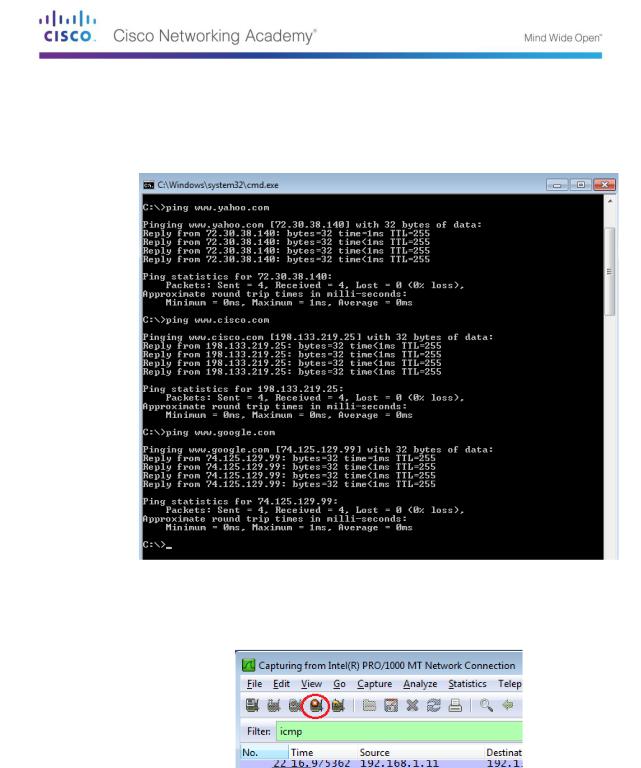
With the capture active, ping the following three website URLs:
www.yahoo.com
www.cisco.com
www.google.com
Note: When you ping the URLs listed, notice that the Domain Name Server (DNS) translates the URL to an IP address. Note the IP address received for each URL.
You can stop capturing data by clicking the Stop Capture icon.
Step 11: Examining and analyzing the data from the remote hosts.
Review the captured data in Wireshark, examine the IP and MAC addresses of the three locations that you pinged. List the destination IP and MAC addresses for all three locations in the space provided.
1st Location: |
IP: _____._____._____._____ MAC: ____:____:____:____:____:____ |
2nd Location: |
IP: _____._____._____._____ MAC: ____:____:____:____:____:____ |
3rd Location: |
IP: _____._____._____._____ MAC: ____:____:____:____:____:____ |
What is significant about this information?
© 2013 Cisco and/or its affiliates. All rights reserved. This document is Cisco Public. Page 54 of 257
__________________________________________________________________________
__________
How does this information differ from the local ping information you received in Part 2?
__________________________________________________________________________
__________
__________________________________________________________________________
__________
Reflection
Why does Wireshark show the actual MAC address of the local hosts, but not the actual MAC address for the remote hosts?
_____________________________________________________________________________
__________
_____________________________________________________________________________
__________
Appendix A: Allowing ICMP Traffic Through a Firewall
If the members of your team are unable to ping your PC, the firewall may be blocking those requests. This appendix describes how to create a rule in the firewall to allow ping requests. It also describes how to disable the new ICMP rule after you have completed the lab.
Step 1: Create a new inbound rule allowing ICMP traffic through the firewall.
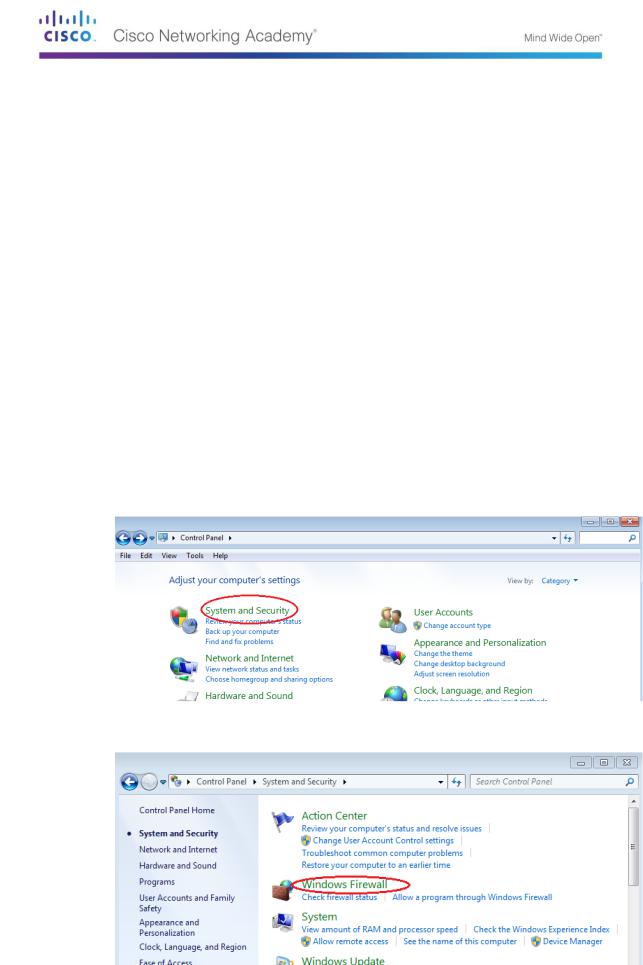
From the Control Panel, click the System and Security option.
From the System and Security window, click Windows Firewall.
© 2013 Cisco and/or its affiliates. All rights reserved. This document is Cisco Public. Page 55 of 257
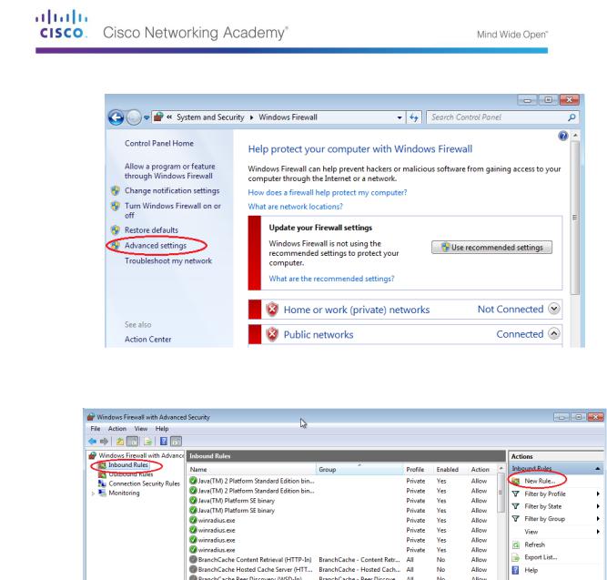
In the left pane of the Windows Firewall window, click Advanced settings.
On the Advanced Security window, choose the Inbound Rules option on the left sidebar and then click New Rule… on the right sidebar.
© 2013 Cisco and/or its affiliates. All rights reserved. This document is Cisco Public. Page 56 of 257
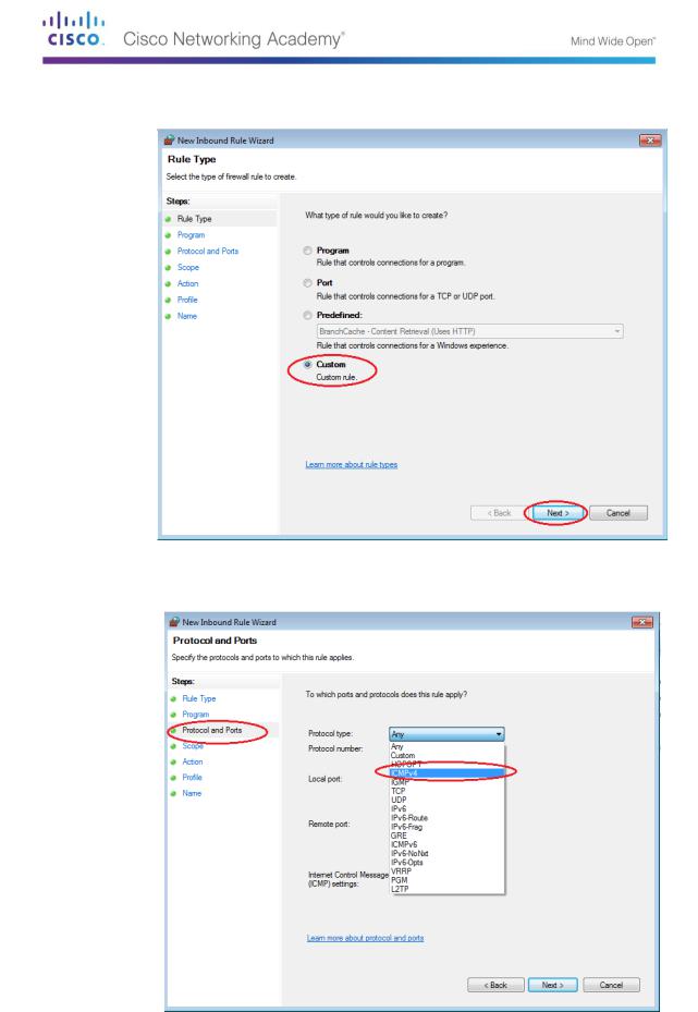
This launches the New Inbound Rule wizard. On the Rule Type screen, click the Custom radio button and click Next
In the left pane, click the Protocol and Ports option and using the Protocol type drop-down menu, select ICMPv4, and then click Next.
In the left pane, click the Name option and in the Name field, type Allow ICMP Requests. Click
Finish.
© 2013 Cisco and/or its affiliates. All rights reserved. This document is Cisco Public. Page 57 of 257
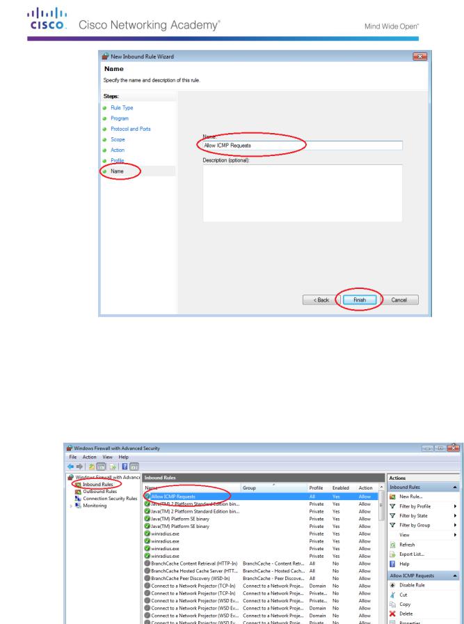
This new rule should allow your team members to receive ping replies from your PC.
Step 2: Disabling or deleting the new ICMP rule.
After the lab is complete, you may want to disable or even delete the new rule you created in Step 1. Using the Disable Rule option allows you to enable the rule again at a later date. Deleting the rule permanently deletes it from the list of Inbound Rules.
On the Advanced Security window, in the left pane, click Inbound Rules and then locate the rule you created in Step 1.
To disable the rule, click the Disable Rule option. When you choose this option, you will see this option change to Enable Rule. You can toggle back and forth between Disable Rule and Enable Rule; the status of the rule also shows in the Enabled column of the Inbound Rules list.
© 2013 Cisco and/or its affiliates. All rights reserved. This document is Cisco Public. Page 58 of 257
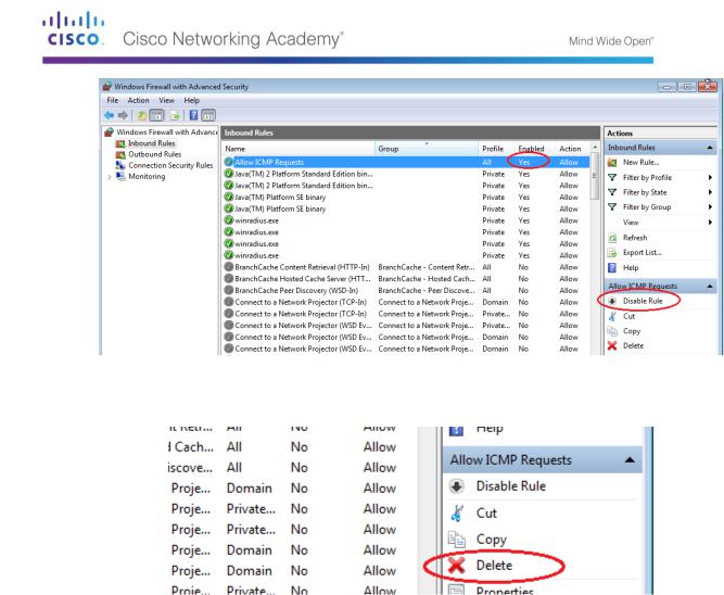
To permanently delete the ICMP rule, click Delete. If you choose this option, you must re-create the rule again to allow ICMP replies.
© 2013 Cisco and/or its affiliates. All rights reserved. This document is Cisco Public. Page 59 of 257

Lab 6 - Identifying Network Devices and Cabling
Objectives
Part 1: Identify Network Devices
Describe the functions and physical characteristics of the network device.
Part 2: Identify Network Media
Describe the functions and physical characteristics of the media.
Background / Scenario
As a member of the networking support staff, you must be able to identify different networking equipment. You must also understand the function of equipment in the appropriate part of the network. In this lab, you will have access to network devices and media. You will identify the type and characteristics of the network equipment and media.
Part 21: Identify Network Devices
Your instructor will provide various network devices for identification. Each will be tagged with an ID number.
Fill in the table below with the device tag ID number, manufacturer, device model, type (hub, switch, and router), functionality (wireless, router, switch, or combination), and other physical characteristics, such as number of interface types. The first line is filled out as a reference.
© 2013 Cisco and/or its affiliates. All rights reserved. This document is Cisco Public. Page 60 of 257