

CCNA_R&S-Student_Lab_Manual
.pdfDRAM configuration is 64 bits wide with parity disabled. 255K bytes of non-volatile configuration memory. 250880K bytes of ATA System CompactFlash 0 (Read/Write) <output omitted>
Technology Package License Information for Module:'c1900'
-----------------------------------------------------------------
Technology |
Technology-package |
Technology-package |
|
|
Current |
Type |
Next reboot |
------------------------------------------------------------------
ipbase |
ipbasek9 |
Permanent |
ipbasek9 |
security |
securityk9 |
Permanent |
securityk9 |
data |
None |
None |
None |
Configuration register is 0x2102
c.Based on the output of the show version command, answer the following questions about the router. If you are examining a different model router, include the information about it here.
1)What is the version of the Cisco IOS and what is the system image filename?
_______________________________________________________________________
_________
2)What is the Bootstrap program version in ROM BIOS?
_______________________________________________________________________
_________
3)How long has the router been running without a restart (also known as its uptime)?
_______________________________________________________________________
_________
4)How much dynamic random-access memory (DRAM) memory does the router have?
_______________________________________________________________________
_________
5)What is the router’s processor board ID number?
_______________________________________________________________________
_________
6)What network interfaces does the router have?
_______________________________________________________________________
_________
7)How much CompactFlash memory for IOS storage is there?
_______________________________________________________________________
_________
8)How much nonvolatile random-access memory (NVRAM) memory for configuration file storage is there?
_______________________________________________________________________
_________
9)What is the setting of the configuration register?
_______________________________________________________________________
_________
©2013 Cisco and/or its affiliates. All rights reserved. This document is Cisco Public.
Page 121 of 257

Step 2: Use the show interface command to examine the network interfaces.
a.Use the show interface gigabitEthernet 0/0 command to see the status of the Gigabit Ethernet 0/0 interface.
Note: After typing part of the command, for example, show interface g, you can use the Tab key on your keyboard to complete the gigabitEthernet command parameter.
Router# show interface gigabitEthernet 0/0
GigabitEthernet0/0 is administratively down, line protocol is down
Hardware is CN Gigabit Ethernet, address is 442b.031a.b9a0 (bia 442b.031a.b9a0)
MTU 1500 bytes, BW 100000 Kbit/sec, DLY 100 usec, reliability 255/255, txload 1/255, rxload 1/255
Encapsulation ARPA, loopback not set Keepalive set (10 sec)
Full Duplex, 100Mbps, media type is RJ45
output flow-control is unsupported, input flow-control is unsupported ARP type: ARPA, ARP Timeout 04:00:00
Last input never, output never, output hang never Last clearing of "show interface" counters never
Input queue: 0/75/0/0 (size/max/drops/flushes); Total output drops: 0 Queueing strategy: fifo
Output queue: 0/40 (size/max)
5 minute input rate 0 bits/sec, 0 packets/sec
5 minute output rate 0 bits/sec, 0 packets/sec
3 packets input, 276 bytes, 0 no buffer Received 0 broadcasts (0 IP multicasts) 0 runts, 0 giants, 0 throttles
0 input errors, 0 CRC, 0 frame, 0 overrun, 0 ignored 0 watchdog, 0 multicast, 0 pause input
0 packets output, 0 bytes, 0 underruns
0 output errors, 0 collisions, 0 interface resets
0 unknown protocol drops
0 babbles, 0 late collision, 0 deferred
0 lost carrier, 0 no carrier, 0 pause output
0 output buffer failures, 0 output buffers swapped out
b.Given the output of the show interface gigabitEthernet 0/0 command depicted above, or using the output from your router, answer the following questions:
What is the hardware type and MAC address of the Gigabit Ethernet interface?
__________________________________________________________________________
__________
What is the interface media type? Is the interface up or down?
__________________________________________________________________________
__________
c.Use the show interfaces serial 0/0/0 command to view the status of the Serial 0/0/0 interface.
Router# show interface serial 0/0/0
Serial0/0/0 is administratively down, line protocol is down Hardware is WIC MBRD Serial
MTU 1500 bytes, BW 1544 Kbit/sec, DLY 20000 usec, reliability 255/255, txload 1/255, rxload 1/255
© 2013 Cisco and/or its affiliates. All rights reserved. This document is Cisco Public. Page 122 of 257

Encapsulation HDLC, loopback not set Keepalive set (10 sec)
Last input 07:41:21, output never, output hang never Last clearing of "show interface" counters never
Input queue: 0/75/0/0 (size/max/drops/flushes); Total output drops: 0 Queueing strategy: fifo
Output queue: 0/40 (size/max)
5 minute input rate 0 bits/sec, 0 packets/sec
5 minute output rate 0 bits/sec, 0 packets/sec
1 packets input, 24 bytes, 0 no buffer Received 1 broadcasts (0 IP multicasts) 0 runts, 0 giants, 0 throttles
0 input errors, 0 CRC, 0 frame, 0 overrun, 0 ignored, 0 abort 0 packets output, 0 bytes, 0 underruns
0 output errors, 0 collisions, 2 interface resets
0 unknown protocol drops
0 output buffer failures, 0 output buffers swapped out
1 carrier transitions
DCD=down DSR=down DTR=down RTS=down CTS=down
d.Given the output command depicted above, answer the following questions: What is the frame encapsulation type?
__________________________________________________________________________
_________
What is the hardware type? Is the interface up or down?
__________________________________________________________________________
_________
Reflection
1.Why might you need to use an EHWIC expansion slot?
_____________________________________________________________________________
__________
2.Why might you need to upgrade the Flash memory?
_____________________________________________________________________________
__________
3.What is the purpose of the mini-USB port?
_____________________________________________________________________________
__________
_____________________________________________________________________________
__________
_____________________________________________________________________________
__________
4.What is the purpose of the ISM/WLAN indicator light on the backplane of the router? What does it refer to?
_____________________________________________________________________________
__________
_____________________________________________________________________________
__________
© 2013 Cisco and/or its affiliates. All rights reserved. This document is Cisco Public. Page 123 of 257

_____________________________________________________________________________
__________
_____________________________________________________________________________
__________
© 2013 Cisco and/or its affiliates. All rights reserved. This document is Cisco Public. Page 124 of 257
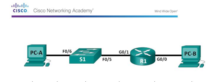
Lab 15 - Building a Switch and Router Network
Topology
Addressing Table
Part 26: |
Part 27: I |
Part 28: IP |
Part 29: Sub |
Part 30: Defau |
evice |
nterface |
Address |
net Mask |
lt Gateway |
|
|
|
|
|
R1 |
G0/0 |
192.168.0.1 |
255.255.255.0 |
N/A |
|
|
|
|
|
|
G0/1 |
192.168.1.1 |
255.255.255.0 |
N/A |
|
|
|
|
|
S1 |
VLAN 1 |
N/A |
N/A |
N/A |
|
|
|
|
|
PC-A |
NIC |
192.168.1.3 |
255.255.255.0 |
192.168.1.1 |
|
|
|
|
|
PC-B |
NIC |
192.168.0.3 |
255.255.255.0 |
192.168.0.1 |
|
|
|
|
|
Objectives
Part 31: Part 1: Set Up the Topology and Initialize Devices
Set up equipment to match the network topology.
Initialize and restart the router and switch.
Part 32: Part 2: Configure Devices and Verify Connectivity
Assign static IP information to the PC interfaces.
Configure the router.
Verify network connectivity.
Part 33: Part 3: Display Device Information
Retrieve hardware and software information from the network devices.
Interpret the output from the routing table.
Display interface information on the router.
Display a summary list of the interfaces on the router and switch.
Background / Scenario
This is a comprehensive lab to review previously covered IOS commands. In this lab, you will cable the equipment as shown in the topology diagram. You will then configure the devices to match the addressing table. After the configurations have been saved, you will verify your configurations by testing for network connectivity.
After the devices have been configured and network connectivity has been verified, you will use IOS commands to retrieve information from the devices to answer questions about your network equipment.
This lab provides minimal assistance with the actual commands necessary to configure the router. However, the required commands are provided in Appendix A. Test your knowledge by trying to configure the devices without referring to the appendix.
© 2013 Cisco and/or its affiliates. All rights reserved. This document is Cisco Public. Page 125 of 257

Note: The routers used with CCNA hands-on labs are Cisco 1941 Integrated Services Routers (ISRs) with Cisco IOS Release 15.2(4)M3 (universalk9 image). The switches used are Cisco Catalyst 2960s with Cisco IOS Release 15.0(2) (lanbasek9 image). Other routers, switches, and Cisco IOS versions can be used. Depending on the model and Cisco IOS version, the commands available and output produced might vary from what is shown in the labs. Refer to the Router Interface Summary Table at the end of this lab for the correct interface identifiers.
Note: Ensure that the routers and switches have been erased and have no startup configurations. Refer to Appendix B for the procedure to initialize and reload a router and switch.
Required Resources
1 Router (Cisco 1941 with Cisco IOS Release 15.2(4)M3 universal image or comparable) 1 Switch (Cisco 2960 with Cisco IOS Release 15.0(2) lanbasek9 image or comparable) 2 PCs (Windows 7, Vista, or XP with terminal emulation program, such as Tera Term) Console cables to configure the Cisco IOS devices via the console ports
Ethernet cables as shown in the topology
Note: The Gigabit Ethernet interfaces on Cisco 1941 routers are autosensing and an Ethernet straight-through cable may be used between the router and PC-B. If using another model Cisco router, it may be necessary to use an Ethernet crossover cable.
Part 9: Set Up Topology and Initialize Devices
Step 1: Cable the network as shown in the topology.
Attach the devices shown in the topology diagram, and cable, as necessary.
Power on all the devices in the topology.
Step 2: Initialize and reload the router and switch.
If configuration files were previously saved on the router and switch, initialize and reload these devices back to their basic configurations. For information on how to initialize and reload these devices, refer to Appendix B.
Part 10: Configure Devices and Verify Connectivity
In Part 2, you will set up the network topology and configure basic settings, such as the interface IP addresses, device access, and passwords. Refer to the Topology and Addressing
Table at the beginning of this lab for device names and address information.
Note: Appendix A provides configuration details for the steps in Part 2. You should attempt to complete Part 2 prior to reviewing this appendix.
Step 3: Assign static IP information to the PC interfaces.
Configure the IP address, subnet mask, and default gateway settings on PC-A.
Configure the IP address, subnet mask, and default gateway settings on PC-B.
Ping PC-B from a command prompt window on PC-A.
Why were the pings not successful?
__________________________________________________________________________
__________
© 2013 Cisco and/or its affiliates. All rights reserved. This document is Cisco Public. Page 126 of 257

Step 4: Configure the router.
Console into the router and enable privileged EXEC mode.
Enter configuration mode.
Assign a device name to the router.
Disable DNS lookup to prevent the router from attempting to translate incorrectly entered commands as though they were host names.
Assign class as the privileged EXEC encrypted password. Assign cisco as the console password and enable login. Assign cisco as the VTY password and enable login. Encrypt the clear text passwords.
Create a banner that warns anyone accessing the device that unauthorized access is prohibited. Configure and activate both interfaces on the router.
Configure an interface description for each interface indicating which device is connected to it. Save the running configuration to the startup configuration file.
Set the clock on the router.
Note: Use the question mark (?) to help with the correct sequence of parameters needed to execute this command.
Ping PC-B from a command prompt window on PC-A.
Were the pings successful? Why?
__________________________________________________________________________
__________
__________________________________________________________________________
__________
__________________________________________________________________________
__________
Part 11: Display Device Information
In Part 3, you will use show commands to retrieve information from the router and switch.
Step 5: Retrieve hardware and software information from the network devices.
Use the show version command to answer the following questions about the router.
What is the name of the IOS image that the router is running?
__________________________________________________________________________
__________
How much DRAM memory does the router have?
__________________________________________________________________________
__________
__________________________________________________________________________
__________
How much NVRAM memory does the router have?
__________________________________________________________________________
__________
How much Flash memory does the router have?
© 2013 Cisco and/or its affiliates. All rights reserved. This document is Cisco Public. Page 127 of 257

__________________________________________________________________________
__________
Use the show version command to answer the following questions about the switch.
What is the name of the IOS image that the switch is running?
__________________________________________________________________________
__________
How much dynamic random access memory (DRAM) does the switch have?
__________________________________________________________________________
__________
How much nonvolatile random-access memory (NVRAM) does the switch have?
__________________________________________________________________________
__________
What is the model number of the switch?
__________________________________________________________________________
__________
Step 6: Display the routing table on the router.
Use the show ip route command on the router to answer the following questions. What code is used in the routing table to indicate a directly connected network? _____
How many route entries are coded with a C code in the routing table? _________
What interface types are associated to the C coded routes?
_____________________________________________________________________________
__________
Step 7: Display interface information on the router.
Use the show interface g0/1 to answer the following questions.
What is the operational status of the G0/1 interface?
_____________________________________________________________________________
__________
What is the Media Access Control (MAC) address of the G0/1 interface?
_____________________________________________________________________________
__________
How is the Internet address displayed in this command?
_____________________________________________________________________________
__________
Step 8: Display a summary list of the interfaces on the router and switch.
There are several commands that can be used to verify an interface configuration. One of the most useful of these is the show ip interface brief command. The command output displays a summary list of the interfaces on the device and provides immediate feedback to the status of each interface.
Enter the show ip interface brief command on the router.
R1# show ip interface brief
Interface |
IP-Address |
OK? Method Status |
Protocol |
|
|
© 2013 Cisco and/or its affiliates. All rights reserved. This document is Cisco Public. Page 128 of 257

Embedded-Service-Engine0/0 |
unassigned |
YES unset |
administratively down |
down |
|
|
|
GigabitEthernet0/0 |
192.168.0.1 |
YES manual up |
|
up |
|
|
|
GigabitEthernet0/1 |
192.168.1.1 |
YES manual up |
|
up |
|
|
|
Serial0/0/0 |
unassigned |
YES unset |
administratively down |
down |
|
|
|
Serial0/0/1 |
unassigned |
YES unset |
administratively down |
down |
|
|
|
R1#
Enter the show ip interface brief command on the switch.
Switch# show ip interface brief
Interface |
IP-Address |
OK? Method Status |
|
|
Protocol |
|
|
|
|
Vlan1 |
unassigned |
YES manual up |
up |
|
FastEthernet0/1 |
unassigned |
YES unset |
down |
down |
FastEthernet0/2 |
unassigned |
YES unset |
down |
down |
FastEthernet0/3 |
unassigned |
YES unset |
down |
down |
FastEthernet0/4 |
unassigned |
YES unset |
down |
down |
FastEthernet0/5 |
unassigned |
YES unset |
up |
up |
FastEthernet0/6 |
unassigned |
YES unset |
up |
up |
FastEthernet0/7 |
unassigned |
YES unset |
down |
down |
FastEthernet0/8 |
unassigned |
YES unset |
down |
down |
FastEthernet0/9 |
unassigned |
YES unset |
down |
down |
FastEthernet0/10 |
unassigned |
YES unset |
down |
down |
FastEthernet0/11 |
unassigned |
YES unset |
down |
down |
FastEthernet0/12 |
unassigned |
YES unset |
down |
down |
FastEthernet0/13 |
unassigned |
YES unset |
down |
down |
FastEthernet0/14 |
unassigned |
YES unset |
down |
down |
FastEthernet0/15 |
unassigned |
YES unset |
down |
down |
FastEthernet0/16 |
unassigned |
YES unset |
down |
down |
FastEthernet0/17 |
unassigned |
YES unset |
down |
down |
FastEthernet0/18 |
unassigned |
YES unset |
down |
down |
FastEthernet0/19 |
unassigned |
YES unset |
down |
down |
FastEthernet0/20 |
unassigned |
YES unset |
down |
down |
FastEthernet0/21 |
unassigned |
YES unset |
down |
down |
FastEthernet0/22 |
unassigned |
YES unset |
down |
down |
FastEthernet0/23 |
unassigned |
YES unset |
down |
down |
FastEthernet0/24 |
unassigned |
YES unset |
down |
down |
GigabitEthernet0/1 |
unassigned |
YES unset |
down |
down |
GigabitEthernet0/2 |
unassigned |
YES unset |
down |
down |
Switch# |
|
|
|
|
Reflection
If the G0/1 interface showed administratively down, what interface configuration command would you use to turn the interface up?
_____________________________________________________________________________
__________
What would happen if you had incorrectly configured interface G0/1 on the router with an IP address of 192.168.1.2?
© 2013 Cisco and/or its affiliates. All rights reserved. This document is Cisco Public. Page 129 of 257
_____________________________________________________________________________
__________
_____________________________________________________________________________
__________
_____________________________________________________________________________
__________
_____________________________________________________________________________
__________
Router Interface Summary Table
|
|
|
Part 34: |
Router Interface Summary |
|
|
|
||
|
|
|
|
|
|
|
|
|
|
Part 35: |
Router |
Part 36: |
Ethernet |
Part 37: |
Ethernet |
Part 38: |
Serial |
Part 39: |
Serial |
Model |
Interface #1 |
Interface #2 |
Interface #1 |
Interface #2 |
|||||
|
|
|
|
|
|
|
|
||
1800 |
|
Fast Ethernet 0/0 |
Fast Ethernet 0/1 |
Serial 0/0/0 |
|
Serial 0/0/1 |
|
||
|
|
(F0/0) |
|
(F0/1) |
|
(S0/0/0) |
|
(S0/0/1) |
|
|
|
|
|
|
|
|
|
||
1900 |
|
Gigabit Ethernet 0/0 |
Gigabit Ethernet 0/1 |
Serial 0/0/0 |
|
Serial 0/0/1 |
|
||
|
|
(G0/0) |
|
(G0/1) |
|
(S0/0/0) |
|
(S0/0/1) |
|
|
|
|
|
|
|
|
|
||
2801 |
|
Fast Ethernet 0/0 |
Fast Ethernet 0/1 |
Serial 0/1/0 |
|
Serial 0/1/1 |
|
||
|
|
(F0/0) |
|
(F0/1) |
|
(S0/1/0) |
|
(S0/1/1) |
|
|
|
|
|
|
|
|
|
||
2811 |
|
Fast Ethernet 0/0 |
Fast Ethernet 0/1 |
Serial 0/0/0 |
|
Serial 0/0/1 |
|
||
|
|
(F0/0) |
|
(F0/1) |
|
(S0/0/0) |
|
(S0/0/1) |
|
|
|
|
|
|
|
|
|
||
2900 |
|
Gigabit Ethernet 0/0 |
Gigabit Ethernet 0/1 |
Serial 0/0/0 |
|
Serial 0/0/1 |
|
||
|
|
(G0/0) |
|
(G0/1) |
|
(S0/0/0) |
|
(S0/0/1) |
|
|
|
|
|
|
|
|
|
|
|
Note: To find out how the router is configured, look at the interfaces to identify the router type and how many interfaces the router has. There is no way to effectively list all the combinations of configurations for each router class. This table includes identifiers for the possible combinations of Ethernet and Serial interfaces in the device. The table does not include any other type of interface, even though a specific router may contain one. An example of this might be an ISDN BRI interface. The string in parenthesis is the legal abbreviation that can be used in Cisco IOS commands to represent the interface.
Appendix A: Configuration Details for Steps in Part 2
Step 1: Configure the PC interfaces.
Configure the IP address, subnet mask, and default gateway settings on PC-A.
© 2013 Cisco and/or its affiliates. All rights reserved. This document is Cisco Public. Page 130 of 257