

Yang Fluidization, Solids Handling, and Processing
.pdfFluidized Bed Scale-up |
95 |
Glicksman et al. (1991) made scaling comparisons between an experimental circulating fluidized bed combustor and a scaled cold model based on the full set of scaling laws. The time-resolved pressure fluctuations and the time-averaged pressure drop were measured. Due to uncertainties in the hot bed solid circulation measurements, the cold bed solids flux was adjusted until the average bed solid fraction matched that of the hot bed. Differences could also be due to the mismatch in the solid-to-gas density ratio between the model and the hot bed. The vertical solid fraction profiles, the probability density function and the Fourier transform of the pressure fluctuations were compared between the hot and cold bed. Good agreement was obtained between the vertical solid fraction profiles except near the top of the beds. It was suggested that the differences in the solid fraction profiles at the top of the bed could be due to protrusions or wall roughness in the hot bed which were not modeled in the cold bed. Good agreement was also obtained in the comparison of the probability density distribution and the Fourier transform of the pressure fluctuations.
Chang and Louge (1992) carried out tests on a circulating bed in which they could vary the gas composition. By combining this with particles of different density and size, they were able to scale a series of different size hot commercial beds with diameters up to five times larger than the cold bed. Comparisons between glass and plastic particles showed identical mean vertical solids fraction profiles. The corresponding pressure fluctuations for plastic and glass are found to scale with ρsgφ dp; one would expect the pressure fluctuations to scale with ρsuo2. This is probably an artifice of the experimental design since Froude number based on particle diameter, uo2/gφ dp , was matched in the comparisons whereas Froude number based on bed diameter could not be matched since the experimental bed diameter was fixed in the tests. The inability to alter the bed diameter also made it impossible to match the D/ dp scaling parameter. Chang and Louge matched a modified form of the full set of scaling laws. Particle sphericity is not explicitly included as an independent parameter, rather it is included with the particle diameter based on a combination of the gas to particle drag coefficient. Their modified parameters are:
Eq. (90)
|
2 |
|
|
|
|
|
|
3 |
|
|
|
D |
G s |
|
ρs |
|
ρ s ρ g (d p φ ) g |
||
|
uo |
|
|
|
|||||
Fr* = |
|
, L* = |
|
, M = |
|
, R = |
|
,and Ar* = |
|
|
|
|
|
|
|||||
gφ d |
p |
d |
p |
φ |
ρ |
u |
o |
ρ |
f |
μ 2 |
|
|
|
s |
|
|
|
96 Fluidization, Solids Handling, and Processing
The values of the parameters matched for scaling are presented in the “Other Parameters” column of Table 7. Steel and glass particles were also compared. The similarity using steel and glass was poor because the bed using the steel particles was choked while the bed with glass particles was not. Yang’s (1983) correlation indicates that choking is a strong function of the Froude number based on bed diameter ( FrD). The value of FrD could not be matched between the beds which caused them to choke under different conditions.
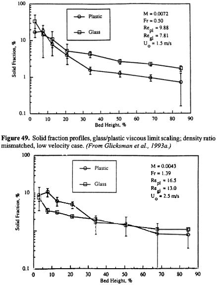
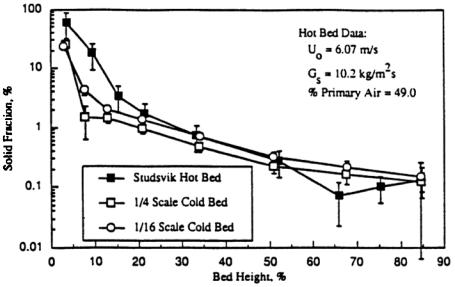
Glicksman et al. (1993a) evaluated the full set of scaling laws for circulating fluidized beds. Solid fraction data were obtained from the 2.5 MWth Studsvik atmospheric CFB prototype. The full set of scaling laws were evaluated through solid fraction profile comparisons between Studsvik and a 1/4 scale cold model. Fairly good agreement was obtained; the profiles most closely matched in the top of the beds. Differences between the profiles were attributed to uncertainty in the hot bed solid flux measurements and to the mismatch in the solid-to-gas density ratio.
The viscous limit scaling laws was also evaluated by Glicksman et al. (1993b) in a series of comparison tests using circulating beds. To compare two cases based on the viscous limit while deliberately mismatching the solid-to gas density ratio, scaling was attempted between glass/steel and glass/plastic (i.e., different density ratios) in the same bed. The average solid fraction profiles, solid fraction probability density functions, and power spectral densities were all in poor agreement. Figure 49 is a sample solid fraction profile comparison based on viscous limit scaling. It is believed the beds were operating near the point of incipient choking condition as predicted by the Yang (1983) correlation. Because this correlation indicates that choking is a strong function of the solid-to- gas density ratio, the viscous limit scaling parameters are unable to model bed hydrodynamics near the boundary between different flow regimes. Figure 50 shows a somewhat better agreement near the top of the bed at higher velocities. They concluded that since low uo is required for the viscous limit scaling to be valid while sufficiently high uo is required to prevent choking, the applicability of the viscous limit scaling parameters for circulating fluidized beds is limited. It was suggested that these scaling parameters may have a wider range of validity in bubbling beds.
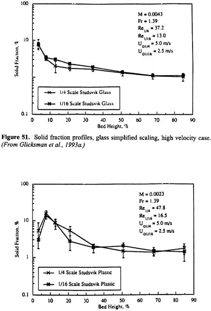
The simplified scaling laws were used by Glicksman et al. (1993b) to compare two geometrically similar beds, one having linear dimensions four times larger than the other. In one series of tests, properly sized plastic particles were used in both beds; in another test series, glass particles were used in the two beds. The average solid fraction profiles showed excellent agreement (Figs. 51 and 52). The probability density functions and power
100 Fluidization, Solids Handling, and Processing
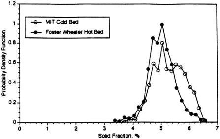
Glicksman et al. (1995) used the simplified scaling parameters to construct a one-half linear scale model of a Foster Wheeler circulating bed combustor pressurized to 14 bar. The combustor has a 20.3 cm inner diameter with an overall height of 8.3 m with both a primary and secondary air supply. The solids recycle rate was determined by a calorimetric balance of a fluidized bed heat exchanger in the return loop of the circulating bed. The cold model, one half scale, used polyethylene plastic particles to match the dimensionless particle size distribution as well as the gas-to-solid density ratio. The time-averaged vertical pressure difference was used to determine the solid fraction distribution in the combustor and the cold model. Figure 54 shows the close agreement between the combustor and the cold model. Three test cases had similar solid fraction versus height profiles. The fourth, operated at low gas velocity and solids recycle rate had a more abrupt decrease of solid fraction with bed height. The cold model reflected the same behavior, as shown in Fig. 55. The probability density function of one pair of time resolved differential pressure measurements is shown in Fig. 56 for the combustor and hot bed; again close agreement is observed. There was some discrepancy near the secondary air inlets. This might be due to fluctuations set up by the bubbling bed heat exchanger upstream of the secondary air inlet to the combustor. The bubbling bed was not duplicated in the cold scale model. Recent experiments have shown close agreement between a Foster Wheeler pressurized circulating bed combustor and a 1/6.5 linear scale model.
11.0CONCLUSIONS
As fluidized beds are scaled up from bench scale to commercial plant size the hydrodynamic behavior of the bed changes, resulting, in many cases, in a loss of performance. Although there have been some studies of the influence of bed diameter on overall performance as well as detailed behavior such as solids mixing and bubble characteristics, generalized rules to guide scale-up are not available. The influence of bed diameter on performance will differ for different flow regimes of fluidization.
Small, properly scaled laboratory models operated at ambient conditions have been shown to accurately simulate the dynamics of large hot bubbling and circulating beds operating at atmospheric and elevated pressures. These models should shed light on the overall operating characteristics and the influence of hydrodynamics factors such as bubble distribution and trajectories. A series of different sized scale models can be used to simulate changes in bed behavior with bed size.

102 Fluidization, Solids Handling, and Processing
Figure 56. Histograms: test condition 2 of Fig. 55. Dimensionless distance up bed (x/H) = 0.80. (From Glicksman et al., 1995.)
The scale models must be carefully designed. Failure to match the important dimensionless parameters will lead to erroneous simulation results. Modeling can be extended to particle convective heat transfer. Wear or erosion of in-bed surfaces can be qualitatively studied, although quantitative assessment requires the identification and simulation of additional wear-related parameters.
Most of the simulation effort has been applied to fluidized bed combustors which use relatively large size particles. Simulation can also be used for other fluidization processes in the petrochemical industry. Research should be undertaken to identify the proper scaling parameters for beds fluidized with smaller particles. Similar simulations may also apply to components such as cyclones.
ACKNOWLEDGMENTS
The author would like to acknowledge the contributions of many present and former M.I.T. students who carried out scaling studies of fluidized beds. Much of the M.I.T. research mentioned in this chapter has
Fluidized Bed Scale-up 103
been sponsored by the Electric Power Research Institute, the National Science Foundation, the U.S. Department of Energy, and the Tennessee Valley Authority.
NOTATIONS
CD |
drag coefficient of sphere |
D |
Bed diameter |
dB |
Bubble diameter |
dc |
Cluster diameter |
dp |
Particle diameter |
dV |
Equivalent bubble diameter |
E |
Local average stress tensor |
f |
Frequency |
F |
Drag force between fluid and particle |
GS |
Solids recycle rate per unit area |
g |
Acceleration of gravity |
L |
Typical bed dimensions |
m |
Coefficient (Eq. 3) |
p |
Pressure |
QB |
Bubble volume flow rate |
tTime
uGas velocity
ub |
Bubble rise velocity |
umf |
Minimum fluidization velocity |
uo |
Superficial gas velocity |
ut |
Terminal velocity |
v |
Particle velocity |
x,y |
Coordinates |
Dimensionless
Ar Archimedes number
Fr Froude number based on L
PSD Dimensionless particle size distribution
Re Reynolds number
104 Fluidization, Solids Handling, and Processing
Greek
βDrag coefficient
δBubble volume fraction
δBoundary layer thickness in a fast bed Distributor plate voidage
εVoid fraction
εc |
Cluster void fraction |
εmf |
Void fraction at minimum fluidization |
ρf |
Fluid density |
ρS |
Solid density |
μFluid viscosity
υFluid kinematic viscosity
Subscripts
( )c |
Commercial bed |
( )m |
Model bed |
Superscripts |
|
( )´ |
Dimensionless |
(−) |
Vector |
REFERENCES
Ackeskog, H. B. R., Almstedt, A. E., and Zakkay, V., “An Investigation of Fluidized-bed Scaling: Heat Transfer Measurements in a Pressurized Fluidized-bed Combustor and a Cold Model Bed,” Chem. Eng. Sci., 48:1459 (1993)
Ake, T. R., and Glicksman, L. R., “Scale Model and Full Scale Test Results of a Circulating Fluidized Bed Combustor,” Proc. 1988 Seminar on Fluidized Bed Comb. Technol. for Utility Appl., EPRI, 1-24-1 (1989)
Almstedt, A. E., and Zakkay, V., “An Investigation of Fluidized-bed Scalingcapacitance Probe Measurements in a Pressurized Fluidized-bed Combustor and a Cold Model Bed,” Chem. Eng. Sci., 45(4):1071 (1990)
Anderson, T. B., and Jackson, R., “A Fluid Mechanical Description of Fluidized Bed,” I & EC Fundamentals, 6:527 (1967)
Arena, U., Cammarota, A., Massimilla, L., and Pirozzi, D., “The Hydrodynamic Behavior of Two Circulating Fluidized Bed Units of Different Size,”
Circulating Fluidized Bed Technol. II, (P. Basu, and J. F. Large, eds.), Pergamon Press, Oxford (1988)