


88 7. PERFUSION BIOREACTORS AND STIMULATION PATTERNS
tored and tightly controlled environmental and operating conditions (e.g., pH, temperature, pressure, nutrient supply, and waste removal).
7.2BIOREACTOR CULTIVATION OF ENGINEERED CARDIAC TISSUE
7.2.1MASS TRANSFER IN 3D CULTURES
In vivo, oxygen and nutrients transport from the blood to the tissues is a diffusive process driven by a gradient of tension. Blood is delivered to every part of the body via vascular networks that serve as transport channels for convective flow and make it possible for diffusive nutrients to transfer across the cellular space and ECM more efficiently. When tissue engineering is performed outside the body (ex vivo) under static cultivation conditions, two main problems arise. First, the existence of a boundary layer around the cell construct decreases nutrients and oxygen diffusion to the construct surface. Second, the diffusion coefficient that is influenced by construct porosity and tortuosity is reduced to an effectiveness coefficient, as described in the following equation:
εp
Deff = DN τ
Where Deff is the effectiveness diffusion coefficient, DN is the nutrient diffusion coefficient and εp and τ are the cell construct porosity and tortuosity, respectively. Taken together, the diffusion limitations cause serious problems in engineering a functional thick tissue. Cell constructs thicker than the diffusion distance suffer from poor tissue survival in the construct core due to anoxic conditions and lack of efficient waste removal.
Adding to this challenge is the relatively high cell density in the tissue engineered cardiac constructs. The consumption rate of nutrients and especially of dissolved oxygen in such a densely packed construct may be greater than molecular diffusion rate, leading to nutrient deprivation in the construct and cell death. Grodzinsky et al formulated a combined equation that generally follows Michaelis-Menten type dependence to describe nutrient concentration distribution L(x) in a tissue, while taking into account the transport rates across a tissue and the nutrient consumption rates by cells [5].
∂L = D ∂2L − ρkL
∂t ∂x2 Km+L
Where D is the diffusion coefficient, k is the maximal uptake rate constant per cell, Km is the saturation constant, ρ is cell density, and x is the distance from the nutrient source.
Bio-inspired by nature, the transport of dissolved oxygen and nutrients can be improved by introducing medium convection to the cultivation system. The resulting nutrient concentration distribution is described then by: convection, diffusion, and consumption:
∂L |
∂L |
|
∂2L |
|
ρkL |
|
|
=Vx |
|
+D |
|
− |
|
∂t |
∂x |
∂x2 |
Km+L |
|||

7.2. BIOREACTOR CULTIVATION OF ENGINEERED CARDIAC TISSUE 89
Where Vx is the velocity of the fluid forced across the construct and transferring the essential molecules along the X-axis.Adding convection to the equation should improve nutrient and dissolved oxygen transport in the entire cell construct in a similar manner to the action of the capillary network in our body.
7.2.2BIOREACTOR AS A SOLUTION FOR MASS TRANSFER CHALLENGE
The first-generation bioreactors for cell construct cultivation were adapted from vessels used to cultivate large volumes of concentrated cell suspensions, such as spinner flasks or rotating vessels. The bioreactors represented different patterns of vessel geometry, scaffold placing, and fluid dynamics to promote efficient fluid mixing and were successful in reducing the boundary layer surrounding the cell construct surface. In these systems, however, molecular diffusion was the main factor influencing the transport of dissolved oxygen and nutrients from the culture medium to the seeded cells in construct. Since oxygen diffusion alone can support only four to seven cell layers, cultivation of cell constructs under these condition resulted in only a 100 μm thick layer of viable and compact tissue (compatible with the oxygen diffusion distance) [6, 7, 8].
7.2.3PERFUSION BIOREACTORS
In order to increase the thickness of viable cardiac tissue above 100 μm, diffusional oxygen limitations have to be overcome and this has been accomplished by the use of perfusion bioreactors. The application of perfusion, by forcing the medium into the entire cell-seeded scaffolds, enables efficient mass transfer of oxygen and other soluble factors throughout the entire developing tissue, similar to the role of the vasculature in tissues.
Perfusion bioreactors operation is based on culture medium convection across a porous cell construct, thus providing a controllable, mechanically active environment for all seeded cells. It was shown that cultivation of engineered tissues in perfusion bioreactors improved the construct size, cellularity, and molecular composition. The bioreactors also made it possible to study effects of
(i) mass transport of growth factors and nutrients,(ii) hydrodynamic load conditions,and (iii) physical stimulation, such as dynamic compression or cyclic stretch, on the developing tissue [9].
The group led by Vunjak-Novakovic was the first to conceive and apply interstitial medium flow in conjunction with porous scaffolds to improve the cardiac patch features.Their initial perfusion bioreactors were commercially available cartridges of 13 mm filter holders, connected to a peristaltic pump. A stainless steel screen was placed at the cartridge inlet to disperse the medium flow over the construct surface, while a nylon mesh was used to fix the downstream side of the construct [10]. Introduction of the pulsatile flow feature in such system improved the contractile properties and enhanced metabolic activity of the cells in the constructs, yet these features were confined mainly to the construct periphery [4, 11]. This may be explained by their use of mesh holders with 60-70% porous structure, resulting in a non-homogeneous environment within the system.
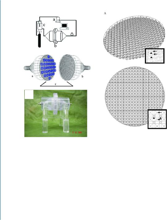
Our group designed a perfusion bioreactor system able to create homogenous medium flow in cell constructs by installing two cell construct-fixing nets, with an open area of 95.8% [12] (Fig. 7.1).
90 7. PERFUSION BIOREACTORS AND STIMULATION PATTERNS
$ |
D |
% |
|
|
D |
|
E
E
F
Figure 7.1: Perfusion bioreactor system. A-a. Overall view: computerized peristaltic pump (a) circulates the medium into the bioreactor vessel (b). The medium then proceeds to the reservoir (c), where it is oxygenated and heated to 37◦C. A-b. Schematic representation of the bioreactor vessel. Two identical halves of the bioreactor (a, b) function as the inlet and the outlet of the cell construct compartment (c). Multiple cell constructs (blue) are fixed between two open pore nets. The angles of both halves were designed to be 60◦ to prevent the breakdown of the incoming flow. A-c. Picture of the bioreactor. B. Architecture of the nets holding the constructs in the bioreactor. Side (a) and upper view (b). The net architecture is an assembly of equally spaced, 380-square-based pyramidal structures (2 mm length × 2 mm height, each) with their heads pointing toward and holding the scaffolds. Four round openings (diameter =1 mm) are located at the corners of the square pyramid. The medium is perfused through these small holes toward the pyramid head at an angle of 60◦. Arrows point to pyramidal heads and arrowheads to the pores at four corners of the base.
7.2. BIOREACTOR CULTIVATION OF ENGINEERED CARDIAC TISSUE 91
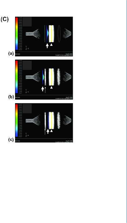
Figure 7.1: Perfusion bioreactor system. C. Profile of the fluid flow velocity in the perfusion bioreactor, constructed via the computerized fluid dynamics software Fluent after solving Navier-Stock equations. The velocity profiles in a perfusion bioreactor with no fluid-distributing mesh (a) or when approaching it in a bioreactor with the flow-distributing mesh (b) reveal a well-developed flow with large-velocity vectors (green) at the center of the bioreactor and smaller ones on the sides (blue). Once past the mesh (c), the flow is interrupted and transforms to undeveloped flow, with equal velocity vectors (blue line) along the bioreactor cross-section. Arrowhead indicates the location of the cellular constructs; thin, long arrows indicate the location of the flow-distributing mesh 1.5 cm upstream from the construct compartment, and thick, short arrows indicate the flow velocity profile. Velocity scale-bar is presented on the left. Dark blue represents the smallest vectors.
92 7. PERFUSION BIOREACTORS AND STIMULATION PATTERNS
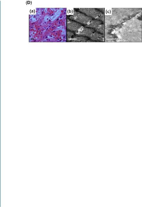
Figure 7.1: Perfusion bioreactor system. D. Histological and ultrastructural morphology of the engineered tissue in perfusion bioreactor. (a) H&E staining reveals massive striation and elongation of the cultured cells. (b) TEM images show defined Z-lines and multiple high-ordered sarcomeres and (c) intercalated disks between adjacent cardiomyocytes. Scale bars: a, 20 μm; b, 1 μm; c, 0.5 μm [12, 13].
The net architecture is an array of equally spaced, 380-square-based micro-pyramidal structures, able to hold multiple scaffolds simultaneously. At the corners of the square pyramid four round openings are positioned, enabling medium convection from the small holes toward the pyramid head, at an angle of 60º, thus sustaining the fluid flow direction (Fig. 7.1B). Using this net architecture, 99.88% of the cell construct volume is perfused by the culture medium. Our perfusion bioreactor was upgraded in another aspect, by insertion of micromesh, designed to disrupt the media flow for a split second before entering the cell constructs, in order to apply equal shear stress along the bioreactor cross-section (Fig. 7.1C). The mesh transforms the developed laminar fluid flow velocity profile into an undeveloped one, having equal velocity vectors along the bioreactor cross-section and subjecting the cellular constructs to an equal shear stress. When using this innovative perfusion bioreactor, the cardiac tissue constructs showed viability of almost 100% of the seeded cells after a seven-day cultivation period, while less than 60% of the cells in static cultures were viable at the end of this period. Furthermore, medium reaching the construct core by perfusion enabled the formation of homogenous, thick (>500 μm), cardiac tissue. Tissue architecture analysis by histochemistry revealed the presence of elongated and aligned cells with massive striation. Ultrastructural morphology analyses presented organized sarcomeres, defined Z-lines, and intercalated disks, resembling the native heart tissue (Fig. 7.1D) [12].
The implementation of perfusion bioreactors in tissue engineering thus has greatly advanced the field, leading to the construction of functioning tissues with thickness much greater than seen before.