

|
|
|
|
Device description |
4.2.1 Content of delivery |
|
|
|
|
|
|
|
|
|
Power Panel C50 |
Retaining clips |
Cable clamps |
|
0TB6102.2110-01 |
7.0" variants |
|
|
|
|
4PPT80.0702-10A |
6 |
|
|
1 |
4PPT80.0702-10B |
6 |
|
|
1 |
4PPT80.0702-16A |
6 |
|
|
1 |
4PPT80.0702-16B |
6 |
|
|
1 |
10.1" variants |
|
|
|
|
4PPT80.101E-10A |
8 |
|
|
1 |
4PPT80.101E-10B |
8 |
|
|
1 |
4PPT80.101E-16A |
8 |
|
|
1 |
4PPT80.101E-16B |
8 |
|
|
1 |
12.1" variants |
|
|
|
|
4PPT80.121E-10A |
8 |
|
|
1 |
4PPT80.121E-10B |
8 |
|
|
1 |
4PPT80.121E-16A |
8 |
|
|
1 |
4PPT80.121E-16B |
8 |
|
|
1 |
15.6" variants |
|
|
|
|
4PPT80.156B-10A |
9 |
2 |
|
1 |
4PPT80.156B-10B |
9 |
2 |
|
1 |
4PPT80.156B-16A |
9 |
2 |
|
1 |
4PPT80.156B-16B |
9 |
2 |
|
1 |
|
|
|
|
|
Order number |
Description |
|
|
|
0TB6102.2110-01 |
Accessory terminal block, 2-pin (3.81), cage clamp terminal block 1.5 mm² |
|
||
Retaining clips |
Accessory set retaining clip for securing the panel in the installation cutout |
|
||
Cable clamps |
Cable clamps for securing / strain relief of the connection lines and connecting the shielding |
|
||
4.2.2 Optional accessories |
|
|
|
|
|
|
|
|
|
Order number |
Description |
|
|
|
0TB6102.2010-01 |
Accessory terminal block, 2-pin (3.81), screw clamp terminal block 1.5 mm² |
|
||
5MMUSB.2048-01 |
USB 2.0 flash drive 2048 MB B&R |
|
|
|
5MMUSB.4096-01 |
USB 2.0 flash drive 4096 MB B&R |
|
|
|
4.3 Technical information
This section contains general technical information about this product:
•System requirements
•Projected capacitive touch (PCT)
•Viewing angles
•Derating of the display brightness
•Surface resistance
4.3.1System requirements
|
Starting with |
Starting with |
Function |
AS version |
AR version |
General support of the Power Panel |
4.7.1 |
4.71 |
*AS ... Automation Studio, AR ... Automation Runtime
Power Panel T80 User's manual V1.01 |
13 |
Device description
4.3.2 Projected capacitive touch (PCT)
Operation |
|
|
Number of fingers |
|
10 |
Glove operation |
|
Yes |
Passive stylus pens |
|
Yes |
Active stylus pens |
|
No |
Error detection |
|
|
Ball of hand |
|
Yes |
Water |
|
Yes |
Front |
|
|
Hardened front glass |
|
Yes |
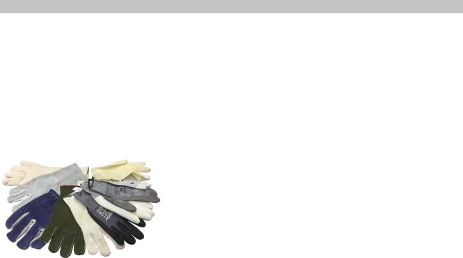
Operation with gloves |
Projected capacitive touch screens (PCT) are suitable for operation with |
|
|
|
|
|
|
or without gloves. |
|
|
A large number of gloves (rubber gloves, light/heavy leather gloves, |
|
|
disposable latex gloves, etc.) are supported. |
|
|
Due to the variety of commercially available gloves, however, B&R can- |
|
|
not guarantee all types. |
Support for stylus pens
Passive stylus pens:
In principle, the Power Panel supports passive stylus pens. Due to the large number of passive stylus pens available on the market, there may be functional differences. For this reason, B&R cannot comprehensively guarantee their functionality.
Active stylus pens are not supported!
Touch actions during cleaning
Touch actions can be triggered during cleaning of the PCT touch screen. If this is not desired, this behavior must be taken into account in the application.
14 |
Power Panel T80 User's manual V1.01 |
Device description
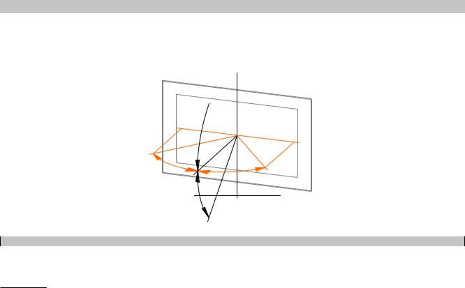
4.3.3 Viewing angles
For the viewing angles values (U, D, R, L) of the display types, see the technical data of the respective device.
U
L
Landscape
R
D 
Legend |
Display viewing angle |
U |
From top |
D |
From bottom |
L |
From left |
R |
From right |
The viewing angles are specified for the horizontal (L, R) and vertical (U, D) axes in reference to the vertical axis of the display. The specified viewing angles above always refer to the standard mounting orientation of the respective Power Panel.
Standard mounting orientation: Interfaces are at the bottom.
4.3.4 Derating the ambient temperature
If the device is installed outside the corresponding specifications, derating the maximum permissible ambient temperature (see "Temperature specifications" in the "Technical data" section) must be taken into account. Depending on the display size, derating must be taken into account under the following conditions:
•Spacing for air circulation is not observed (see "Installation instructions" on page 29).
•Permissible mounting orientations are not observed (see "Mounting orientations" on page 31).
•Derating depends on the display brightness (see "Derating of the display brightness" on page 16).
The following derating must be taken into account during commissioning:
|
|
|
Panel size |
|
|
Condition for derating |
7.0" |
10.1" |
|
12.1" |
15.6" |
Spacing for air circulation not observed |
10°C |
10°C |
|
10°C |
10°C |
Deviation from permissible mounting orientations (e.g. horizon- |
- |
5°C |
|
5°C |
5°C |
tal) |
|
|
|
|
|
High display brightness |
- |
- |
|
- |
Up to 10°C |
Max. derating (all conditions apply) |
10°C |
15°C |
|
15°C |
25°C |
If one or more of the above conditions apply, the device is permitted to be derated up to the maximum operating temperature2) minus the specified derating temperatures.
If several conditions apply, the individual derating values must be added together.
2) See ambient conditions in the technical data.
Power Panel T80 User's manual V1.01 |
15 |
Device description
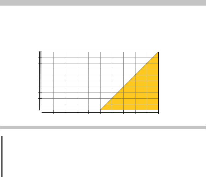
4.3.5 Derating of the display brightness
Display brightness of 15.6" variants
Operating the display at the maximum ambient temperature and maximum display brightness results in impairments in the display. The following derating of the display brightness must therefore be observed:
T [°C]
10 |
|
|
|
|
|
|
|
|
|
|
9 |
|
|
|
|
|
|
|
|
|
|
8 |
|
|
|
|
|
|
|
|
|
|
7 |
|
|
|
|
|
|
|
|
|
|
6 |
|
|
|
|
|
|
|
|
|
|
5 |
|
|
|
|
|
|
|
|
|
|
4 |
|
|
|
|
|
|
|
|
|
|
3 |
|
|
|
|
|
|
|
|
|
|
2 |
|
|
|
|
|
|
|
|
|
|
1 |
|
|
|
|
|
|
|
|
|
|
0 |
|
|
|
|
|
|
|
|
|
|
0 |
10 |
20 |
30 |
40 |
50 |
60 |
70 |
80 |
90 |
100 DB [%] |
|
|
|
|
|
Diagram legend |
|
|
|
|
|
DB [%] Display brightness (DB) in percent |
|
|
|
|
T [°C] |
Derating in °C |
|
|
||
Information:
The display brightness can be derated in two ways:
1)Reducing the display brightness according to the max. ambient temperature.
2)Observing the maximum permissible ambient temperature for the selected display brightness.
In addition to this derating, a further derating must be observed depending on the installation conditions (see "Derating the ambient temperature" on page 15).
4.3.6 Surface resistance
Chemical resistance of the front glass per ASTM D 1308-02 and ASTM F 1598-95 for an exposure time of 24 hours without visible changes:
• |
Acetone |
• |
Vinegar |
• |
Naphtha |
• |
Alkaline cleaning agents |
• |
Ethanol |
• |
Caustic soda 5% |
• |
Ammonia 5% |
• |
Grease |
• |
Nitric acid 70% |
• |
Gasoline (unleaded) |
• |
Ammonia-based glass cleaners |
• |
Hydrochloric acid 5% |
• |
Beer |
• |
Sidolin glass cleaner |
• |
Lubricants |
• |
Brake fluid |
• |
Graphite |
• |
Sulphuric acid 40% |
• Chlorine-alkaline cleaning and disin- |
• |
Hydraulic fluid (Skydrol) |
• Suntan oil and UV radiation |
||
• |
fecting agents (pH value min. 11) 1.5% |
• |
Isopropanol |
• |
Cooking oil |
Hydrogen chloride 6% |
• |
Coffee |
• |
Stamping ink |
|
• |
Coca-Cola |
• |
Ink |
• |
Tea |
• |
Diesel |
• |
Lysol |
• |
Turpentine |
• |
Diesel oil |
• |
Methylbenzene |
• Turpentine oil replacement (thinner) |
|
• |
Dimethylbenzene |
• |
Methyl ethyl ketone |
• |
Trichloroethylene |
16 |
Power Panel T80 User's manual V1.01 |