


Commissioning
5.1.5 Grounding (functional ground)
Disturbances are discharged effectively via a grounding clip. For additional information about electromagnetic compatibility, see the INSTALLATIONS / EMC GUIDE user's manual (MAEMV-ENG on the B&R website www.br-automation.com).
Notice!
Possible malfunction of interfaces and touch screen!
If functional ground is not present, faults in interface communication and touch screen functionality can occur.
The device is only permitted to be operated if properly grounded.
Grounding in the control cabinet
Ground connection
Control cabinet
Grounding rail
≥4 mm²
Figure: Grounding in the control cabinet
Notice!
The ground connection of the device must be low impedance and connected to ground (e.g. grounding rail in the control cabinet) using a short path.
5.1.6 Securing the connecting cables
On Power Panel variants with 15.6" display size, cables can be relieved of tensile stress using the cable clamps provided on the back of the device.
For all other Power Panel variants, an appropriate method for securing the connecting cables in the vicinity of the device (control cabinet, machine, etc.) must be provided.
Cable clamps
5.1.7 Requirements for the cables used
Notice!
To meet the UL certification requirements, copper cables must be used that are designed for an operating temperature >70°C.
32 |
Power Panel T80 User's manual V1.01 |
Commissioning
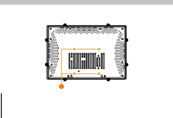
5.1.8 VESA mount
The Power Panel has 4 threaded inserts (1) to accept a VESA mount:
1 |
Notice!
Standard: VESA 100
Maximum screw-in depth of the mounting screws: 8 mm
Select screws of appropriate length to prevent damage to the device.
Power Panel T80 User's manual V1.01 |
33 |