


PROGRAMMING WITH THE X87 FPU
The x87 FPU executes instructions from the processor’s normal instruction stream. The state of the x87 FPU is independent from the state of the basic execution environment (see Chapter 3 and Chapter 7) and from the state of SSE/SSE2/SSE3 extensions (described in Chapters 10, 11 and 12).
However, the x87 FPU and Intel MMX technology share state because the MMX registers are aliased to the x87 FPU data registers. Therefore, when writing code that uses x87 FPU and MMX instructions, the programmer must explicitly manage the x87 FPU and MMX state (see Section 9.5, “Compatibility with x87 FPU Architecture”).
8.1.1x87 FPU in 64-Bit Mode and Compatibility Mode
In compatibility mode and 64-bit mode, x87 FPU instructions function like they do in protected mode. Memory operands are specified using the ModR/M, SIB encoding that is described in Section 3.7.5.
8.1.2x87 FPU Data Registers
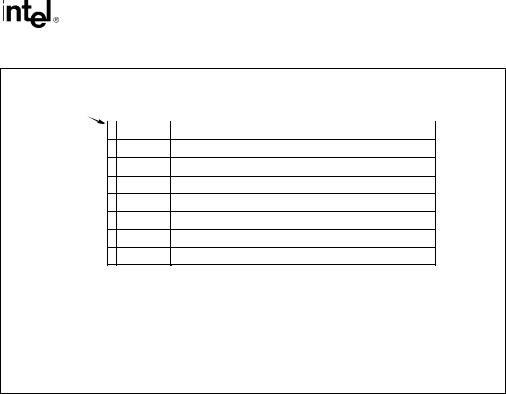
The x87 FPU data registers (shown in Figure 8-1) consist of eight 80-bit registers. Values are stored in these registers in the double extended-precision floating-point format shown in Figure 4-3. When floating-point, integer, or packed BCD integer values are loaded from memory into any of the x87 FPU data registers, the values are automatically converted into double extendedprecision floating-point format (if they are not already in that format). When computation results are subsequently transferred back into memory from any of the x87 FPU registers, the results can be left in the double extended-precision floating-point format or converted back into a shorter floating-point format, an integer format, or the packed BCD integer format. (See Section 8.2, “x87 FPU Data Types” for a description of the data types operated on by the x87 FPU.)
8-2 Vol. 1
PROGRAMMING WITH THE X87 FPU
|
|
|
Data Registers |
|
Sign 79 78 |
64 63 |
0 |
||
R7 |
Exponent |
Significand |
|
|
R6
R5
R4
R3
R2
R1
R0
15 |
0 |
47 |
|
|
0 |
|||
|
|
Control |
|
|
Last Instruction Pointer |
|
|
|
|
|
Register |
|
|
|
|
||
|
|
|
|
|
|
|
|
|
|
|
|
|
|
|
|
|
|
|
|
Status |
|
|
Last Data (Operand) Pointer |
|
|
|
|
|
Register |
|
|
|
|
||
|
|
|
|
|
|
|
|
|
|
|
|
|
|
10 |
0 |
||
|
|
Tag |
|
|
||||
|
|
Register |
|
|
|
Opcode |
|
|
|
|
|
|
|
|
|
|
|
|
|
|
|
|
|
|
|
|
Figure 8-1. x87 FPU Execution Environment
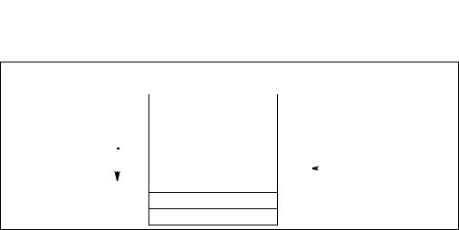
The x87 FPU instructions treat the eight x87 FPU data registers as a register stack (see Figure 8-2). All addressing of the data registers is relative to the register on the top of the stack. The register number of the current top-of-stack register is stored in the TOP (stack TOP) field in the x87 FPU status word. Load operations decrement TOP by one and load a value into the new top- of-stack register, and store operations store the value from the current TOP register in memory and then increment TOP by one. (For the x87 FPU, a load operation is equivalent to a push and a store operation is equivalent to a pop.) Note that load and store operations are also available that do not push and pop the stack.
Vol. 1 8-3
PROGRAMMING WITH THE X87 FPU
|
|
|
FPU Data Register Stack |
|
|
|
|
|
7 |
|
|
|
|
Growth |
6 |
|
|
|
|
|
5 |
|
ST(2) |
|
|
||
Stack |
|
|
|
|||
|
|
4 |
|
ST(1) |
|
Top |
|
|
|
|
|||
|
|
3 |
|
|
|
|
|
|
|
ST(0) |
|
011B |
|
|
|
|
|
|||
|
|
2 |
|
|
|
|
|
|
|
|
|
|
|
1
0
Figure 8-2. x87 FPU Data Register Stack
If a load operation is performed when TOP is at 0, register wraparound occurs and the new value of TOP is set to 7. The floating-point stack-overflow exception indicates when wraparound might cause an unsaved value to be overwritten (see Section 8.5.1.1, “Stack Overflow or Underflow Exception (#IS)”).
Many floating-point instructions have several addressing modes that permit the programmer to implicitly operate on the top of the stack, or to explicitly operate on specific registers relative to the TOP. Assemblers support these register addressing modes, using the expression ST(0), or simply ST, to represent the current stack top and ST(i) to specify the ith register from TOP in the stack (0 ≤ i ≤ 7). For example, if TOP contains 011B (register 3 is the top of the stack), the following instruction would add the contents of two registers in the stack (registers 3 and 5):
FADD ST, ST(2);
Figure 8-3 shows an example of how the stack structure of the x87 FPU registers and instructions are typically used to perform a series of computations. Here, a two-dimensional dot product is computed, as follows:
1.The first instruction (FLD value1) decrements the stack register pointer (TOP) and loads the value 5.6 from memory into ST(0). The result of this operation is shown in snap-
shot (a).
2.The second instruction multiplies the value in ST(0) by the value 2.4 from memory and stores the result in ST(0), shown in snap-shot (b).
3.The third instruction decrements TOP and loads the value 3.8 in ST(0).
4.The fourth instruction multiplies the value in ST(0) by the value 10.3 from memory and stores the result in ST(0), shown in snap-shot (c).
5.The fifth instruction adds the value and the value in ST(1) and stores the result in ST(0), shown in snap-shot (d).
8-4 Vol. 1

|
|
|
|
|
|
|
|
PROGRAMMING WITH THE X87 FPU |
|||||
|
|
|
|
|
|
|
|
|
|
|
|
|
|
|
|
|
Computation |
|
|
|
|
|
|
|
|
||
|
|
|
Dot Product = (5.6 x 2.4) + (3.8 x 10.3) |
|
|
|
|
|
|||||
|
|
|
Code: |
|
|
|
|
|
|
|
|
||
|
|
|
FLD |
value1 ;(a) value1 = 5.6 |
|
|
|
|
|
||||
|
|
|
FMUL value2 ;(b) value2 = 2.4 |
|
|
|
|
|
|||||
|
|
|
FLD |
value3 ; value3 = 3.8 |
|
|
|
|
|
||||
|
|
|
FMUL value4 ;(c)value4 = 10.3 |
|
|
|
|
|
|||||
|
|
|
FADD ST(1) |
;(d) |
|
|
|
|
|
|
|||
(a) |
|
(b) |
|
(c) |
|
|
(d) |
|
|
||||
R7 |
|
|
R7 |
|
|
R7 |
|
|
|
R7 |
|
|
|
R6 |
|
|
R6 |
|
|
R6 |
|
|
|
R6 |
|
|
|
R5 |
|
|
R5 |
|
|
R5 |
|
|
|
R5 |
|
|
|
R4 |
|
5.6 |
ST(0) R4 |
|
13.44 |
ST(0) R4 |
|
13.44 |
ST(1) |
R4 |
|
13.44 |
ST |
R3 |
|
|
R3 |
|
|
R3 |
|
39.14 |
ST(0) |
R3 |
|
52.58 |
ST |
R2 |
|
|
R2 |
|
|
R2 |
|
|
|
R2 |
|
|
|
R1 |
|
|
R1 |
|
|
R1 |
|
|
|
R1 |
|
|
|
R0 |
|
|
R0 |
|
|
R0 |
|
|
|
R0 |
|
|
|
|
|
|
|
|
|
|
|
|
|
|
|
|
|
Figure 8-3. Example x87 FPU Dot Product Computation
The style of programming demonstrated in this example is supported by the floating-point instruction set. In cases where the stack structure causes computation bottlenecks, the FXCH (exchange x87 FPU register contents) instruction can be used to streamline a computation.
8.1.2.1Parameter Passing With the x87 FPU Register Stack
Like the general-purpose registers, the contents of the x87 FPU data registers are unaffected by procedure calls, or in other words, the values are maintained across procedure boundaries. A calling procedure can thus use the x87 FPU data registers (as well as the procedure stack) for passing parameter between procedures. The called procedure can reference parameters passed through the register stack using the current stack register pointer (TOP) and the ST(0) and ST(i) nomenclature. It is also common practice for a called procedure to leave a return value or result in register ST(0) when returning execution to the calling procedure or program.
When mixing MMX and x87 FPU instructions in the procedures or code sequences, the programmer is responsible for maintaining the integrity of parameters being passed in the x87 FPU data registers. If an MMX instruction is executed before the parameters in the x87 FPU data registers have been passed to another procedure, the parameters may be lost (see Section 9.5, “Compatibility with x87 FPU Architecture”).
Vol. 1 8-5