


ABOUT THIS MANUAL
Appendix A — EFLAGS Cross-Reference. Summarizes how the IA-32 instructions affect the flags in the EFLAGS register.
Appendix B — EFLAGS Condition Codes. Summarizes how conditional jump, move, and ‘byte set on condition code’ instructions use condition code flags (OF, CF, ZF, SF, and PF) in the EFLAGS register.
Appendix C — Floating-Point Exceptions Summary. Summarizes exceptions raised by the x87 FPU floating-point and SSE/SSE2/SSE3 floating-point instructions.
Appendix D — Guidelines for Writing x87 FPU Exception Handlers. Describes how to design and write MS-DOS* compatible exception handling facilities for FPU exceptions (includes software and hardware requirements and assembly-language code examples). This appendix also describes general techniques for writing robust FPU exception handlers.
Appendix E — Guidelines for Writing SIMD Floating-Point Exception Handlers. Gives guidelines for writing exception handlers for exceptions generated by SSE/SSE2/SSE3 floatingpoint instructions.
1.3NOTATIONAL CONVENTIONS
This manual uses specific notation for data-structure formats, for symbolic representation of instructions, and for hexadecimal and binary numbers. This notation is described below.
1.3.1Bit and Byte Order
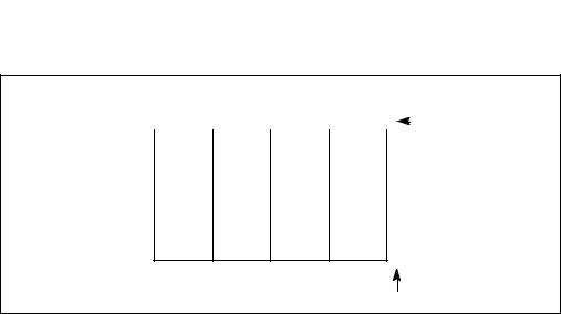
In illustrations of data structures in memory, smaller addresses appear toward the bottom of the figure; addresses increase toward the top. Bit positions are numbered from right to left. The numerical value of a set bit is equal to two raised to the power of the bit position. IA-32 processors are “little endian” machines; this means the bytes of a word are numbered starting from the least significant byte. See Figure 1-1.
Vol. 1 1-3
ABOUT THIS MANUAL
Highest |
|
Data Structure |
|
|
|
|
|
|
|||
Address 31 |
24 |
23 |
16 15 |
8 7 |
0 |
28 |
|
Bit offset |
|||
|
|||||||||||
|
|
|
|
|
|
|
|
|
|
|
|
|
|
|
|
|
|
|
|
|
24 |
|
|
|
|
|
|
|
|
|
|
|
20 |
|
|
|
|
|
|
|
|
|
|
|
16 |
|
|
|
|
|
|
|
|
|
|
|
12 |
|
|
|
|
|
|
|
|
|
|
|
8 |
|
|
|
|
|
|
|
|
|
|
|
4 |
|
|
|
|
Byte 3 |
Byte 2 |
Byte 1 |
Byte 0 |
|
|
0 |
|
|
|
Lowest
Address
Byte Offset
Figure 1-1. Bit and Byte Order
1.3.2Reserved Bits and Software Compatibility
In many register and memory layout descriptions, certain bits are marked as reserved. When bits are marked as reserved, it is essential for compatibility with future processors that software treat these bits as having a future, though unknown, effect. The behavior of reserved bits should be regarded as not only undefined, but unpredictable.
Software should follow these guidelines in dealing with reserved bits:
•Do not depend on the states of any reserved bits when testing the values of registers that contain such bits. Mask out the reserved bits before testing.
•Do not depend on the states of any reserved bits when storing to memory or to a register.
•Do not depend on the ability to retain information written into any reserved bits.
•When loading a register, always load the reserved bits with the values indicated in the documentation, if any, or reload them with values previously read from the same register.
NOTE
Avoid any software dependence upon the state of reserved bits in IA-32 registers. Depending upon the values of reserved register bits will make software dependent upon the unspecified manner in which the processor handles these bits. Programs that depend upon reserved values risk incompatibility with future processors.
1.3.3Instruction Operands
When instructions are represented symbolically, a subset of the IA-32 assembly language is used. In this subset, an instruction has the following format,
1-4 Vol. 1

ABOUT THIS MANUAL
label: mnemonic argument1, argument2, argument3 where:
•A label is an identifier which is followed by a colon.
•A mnemonic is a reserved name for a class of instruction opcodes which have the same function.
•The operands argument1, argument2, and argument3 are optional. There may be from zero to three operands, depending on the opcode. When present, they take the form of either literals or identifiers for data items. Operand identifiers are either reserved names of registers or are assumed to be assigned to data items declared in another part of the program (which may not be shown in the example).
When two operands are present in an arithmetic or logical instruction, the right operand is the source and the left operand is the destination.
For example:
LOADREG: MOV EAX, SUBTOTAL
In this example, LOADREG is a label, MOV is the mnemonic identifier of an opcode, EAX is the destination operand, and SUBTOTAL is the source operand. Some assembly languages put the source and destination in reverse order.
1.3.4Hexadecimal and Binary Numbers
Base 16 (hexadecimal) numbers are represented by a string of hexadecimal digits followed by the character H (for example, 0F82EH). A hexadecimal digit is a character from the following set: 0, 1, 2, 3, 4, 5, 6, 7, 8, 9, A, B, C, D, E, and F.
Base 2 (binary) numbers are represented by a string of 1s and 0s, sometimes followed by the character B (for example, 1010B). The “B” designation is only used in situations where confusion as to the type of number might arise.
1.3.5Segmented Addressing
The processor uses byte addressing. This means memory is organized and accessed as a sequence of bytes. Whether one or more bytes are being accessed, a byte address is used to locate the byte or bytes memory. The range of memory that can be addressed is called an address space.
The processor also supports segmented addressing. This is a form of addressing where a program may have many independent address spaces, called segments. For example, a program can keep its code (instructions) and stack in separate segments. Code addresses would always refer to the code space, and stack addresses would always refer to the stack space. The following notation is used to specify a byte address within a segment:
Segment-register:Byte-address
Vol. 1 1-5

ABOUT THIS MANUAL
For example, the following segment address identifies the byte at address FF79H in the segment pointed by the DS register:
DS:FF79H
The following segment address identifies an instruction address in the code segment. The CS register points to the code segment and the EIP register contains the address of the instruction.
CS:EIP
1.3.6A New Syntax for CPUID, CR, and MSR Values
Obtain feature flags, status, and system information by using the CPUID instruction, by checking control register bits, and by reading model-specific registers. We are moving toward a new syntax to represent this information. See Figure 1-2.
1-6 Vol. 1