

Cisco. Fundamentals Network Design - Cisco Press
.pdfQuality of Service Requirements
Buffering can also be performed within the network itself. Consider a client that connects to a video server. During the video playback session, data moving from the video server to the client can be buffered by the network interface cards and the video decompressor. In this case, buffering acts as a regulator to offset inherent irregularities (latency/jitter) that occur during transmission. The overall effect is that even though the traffic may be bursty coming over the network, the video image is not impaired because the buffers store incoming data and then regulate the flow to the display card.
Buffers can play a large role in displaying video, especially over existing networks, but because they are not large enough to accommodate the entire audio or video file, the use of buffers cannot guarantee jitter-free delivery. For that reason, multimedia networks should also make use of techniques that minimize jitter.
One way of providing predictable performance is to increase line speeds to assure that adequate bandwidth is available during peak traffic conditions. This approach may be reasonable for backbone links, but it may not be cost effective for other links. A more cost-effective approach may be to use lower-speed lines and give mission-critical data priority over less critical transmissions during peak traffic conditions through the use of queuing techniques. The Cisco IOS software offers the following queuing strategies:
•
•
•
Priority Queuing
Custom Queuing
Weighted Fair Queuing
Priority Queuing
Priority queuing allows the network administrator to define four priorities of traffic—high, normal, medium, and low—on a given interface. As traffic comes into the router, it is assigned to one of the four output queues. Packets on the highest priority queue are transmitted first. When that queue empties, packets on the next highest priority queue are transmitted, and so on.
Priority queuing ensures that during congestion, the highest-priority data is not delayed by lower-priority traffic. Note that, if the traffic sent to a given interface exceeds the bandwidth of that interface, lower-priority traffic can experience significant delays.
Custom Queuing
Custom queuing allows the network administrator to reserve a percentage of bandwidth for specified protocols. Cisco IOS Software Release 11.0 allows the definition of up to 16 output queues for normal data (including routing packets) with a separate queue for system messages, such as LAN keepalive messages. The router services each queue sequentially, transmitting a configurable percentage of traffic on each queue before moving on to the next queue. Custom queuing guarantees that mission-critical data is always assigned a certain percentage of the bandwidth but also assures predictable throughput for other traffic. For that reason, custom queuing is recommended for networks that need to provide a guaranteed level of service for all traffic.
Custom queuing works by determining the number of bytes that should be transmitted from each queue, based on the interface speed and the configured percentage. When the calculated byte count from a given queue has been transmitted, the router completes transmission of the current packet and moves on to the next queue, servicing each queue in a round-robin fashion.
With custom queuing, unused bandwidth is dynamically allocated to any protocol that requires it. For example, if SNA is allocated 50 percent of the bandwidth but uses only 30 percent, the next protocol in the queue can take up the extra 20 percent until SNA requires it. Additionally, custom queuing maintains the predictable throughput of dedicated lines by efficiently using packetswitching technologies such as Frame Relay.
Designing Internetworks for Multimedia 13-19

Using Networked Multimedia Applications
Weighted Fair Queuing
Weighted fair queuing was introduced with Cisco IOS Software Release 11.0. Weighted fair queuing is a traffic priority management algorithm that identifies conversations (traffic streams) and then breaks up the streams of packets that belong to each conversation to ensure that capacity is shared fairly between individual conversations. By examining fields in the packet header, the algorithm automatically separates conversations.
Conversations are sorted into two categories—those that are attempting to use a lot of bandwidth with respect to the interface capacity (for example, FTP) and those that need less (for example, interactive traffic). For streams that use less bandwidth, the queuing algorithm always attempts to provide access with little or no queuing and shares the remaining bandwidth between the other conversations. In other words, low-bandwidth traffic has effective priority over high-bandwidth traffic, and high-bandwidth traffic shares the transmission service proportionally.
Weighted fair queuing provides an automatic way of stabilizing network behavior during congestion and results in increased performance and reduced retransmission. In most cases, weighted fair queuing provides smooth end-to-end performance over a given link and, in some cases, may resolve link congestion without an expensive increase in bandwidth.
Note Weighted fair queuing is enabled by default on most serial interfaces; priority queuing or custom queuing can be configured instead. By default, weighted fair queuing is disabled on serial interfaces that are configured for X.25, LAPB, and SDLC, and on all LAN interfaces.
Bandwidth Requirements
Bandwidth requirements for network multimedia applications can range anywhere from 100 Kbps to 70 or 100 Mbps. Figure 13-11 shows the amount of bandwidth that the various types of network multimedia applications require.
Figure 13-11 |
|
Network bandwidth usage. |
|
|
|
||||||||||||||||||||
|
|
|
|
|
|
|
|
|
|
|
|
|
|
|
|
|
|
|
|
|
|
|
|
|
|
|
|
Shared |
|
Video |
|
|
Video |
Video on |
|
Imaging |
|
Virtual |
|||||||||||||
|
|
Application |
|
|
|
Confer- |
Demand |
|
|
|
|
Reality |
|||||||||||||
|
|
|
|
|
|
|
|
|
|
|
|
|
|
encing |
|
|
|
|
|
|
|
|
|
||
|
|
|
|
|
|
|
|
|
|
|
|
|
|
|
|
|
|
|
|
|
|
|
|
|
|
|
|
|
|
|
|
|
|
|
|
MPEG |
|
video |
|
|
|
Imaging |
|
|
Virtual reality |
|
|||||
|
|
|
|
|
|
|
|
|
|
|
|
|
|
|
|
|
|||||||||
|
|
|
|
|
|
|
|
|
|
|
|
|
|
|
|
|
|
|
|
||||||
|
|
|
|
|
|
|
|
|
|
|
|
|
|
|
|
|
|
|
|
||||||
|
|
|
|
|
|
|
|
|
|
|
|
|
|
|
|
|
|
|
|
|
|
||||
|
|
|
|
|
|
|
|
|
|
|
|
|
|
|
|
|
|
|
|
|
|
||||
|
|
|
|
|
|
|
|
|
|
|
|
|
|
|
|
|
|
|
|
||||||
|
|
|
Distance |
|
|
learning |
|
|
|
|
|
|
|
|
|
|
|
|
|||||||
|
|
|
|
|
|
|
|
|
|
|
|
|
|
||||||||||||
|
|
|
|
|
|
|
|
|
|
|
|
|
|
|
|||||||||||
Conferencing |
|
|
|
|
|
|
|
|
|
|
|
|
|
|
|
|
|
|
|
|
|||||
|
|
|
|
|
|
|
|
|
|
|
|
|
|
|
|
|
|
|
|
||||||
|
|
|
|
|
|
|
|
|
|
|
|
|
|
|
|
|
|
|
|
|
|
|
|
|
|
|
|
|
|
|
|
|
|
|
|
|
|
Still video |
|
|
|
|
|
|
|
|
|
||||
|
|
|
|
|
|
|
|
|
|
|
|
|
|
|
|
|
|
|
|
|
|
|
|
|
|
|
|
|
|
|
Speech |
|
|
|
|
|
|
|
|
|
|
|
|
|
|
|
|||||
|
|
|
|
|
|
|
|
|
|
|
|
|
|
|
|
|
|
|
|
|
|
|
|
|
|
|
|
|
|
Shared |
whiteboard |
|
|
|
|
|
|
|
|
|
|||||||||||
|
|
|
|
|
|
|
|
|
|
|
|
|
|
|
|
|
|
|
|
|
|
|
|
|
|
|
|
|
|
|
100 kbps |
|
|
1 Mbps |
|
10 Mbps |
100 Mbps |
||||||||||||||
13-20 Cisco CCIE Fundamentals: Network Design

Understanding Multicasting
As Figure 13-11 indicates, the type of application has a direct impact on the amount of LAN or WAN bandwidth needed. Assuming that bandwidth is limited, the choice is either to select a lower quality video application that works within the available bandwidth, or consider modifying the network infrastructure to deliver more overall bandwidth.
Understanding Multicasting
Traditional network applications, including most of today’s network multimedia applications, involve communication only between two computers. A two-user videoconferencing session using Intel ProShare, for example, is a strictly unicast transaction. However, a new breed of network multimedia applications, such as LAN TV, desktop conferencing, corporate broadcasts, and collaborative computing, requires simultaneous communication between groups of computers. This process is known generically as multipoint communications.
When implementing multipoint network multimedia applications, it is important to understand the traffic characteristics of the application in use. In particular, the network designer needs to know whether an application uses unicast, broadcast, or multicast transmission facilities, defined as follows:
•Unicast—In a unicast design, applications can send one copy of each packet to each member of the multipoint group. This technique is simple to implement, but it has significant scaling restrictions if the group is large. In addition, unicast applications require extra bandwidth, because the same information has to be carried multiple times—even on shared links.
•Broadcast—In a broadcast design, applications can send one copy of each packet and address it to a broadcast address. This technique is even simpler than unicast for the application to implement. However, if this technique is used, the network must either stop broadcasts at the LAN boundary (a technique that is frequently used to prevent broadcast storms) or send the broadcast everywhere. Sending the broadcast everywhere is a significant burden on network resources if only a small number of users actually want to receive the packets.
•Multicast—In a multicast design, applications can send one copy of each packet and address it to a group of computers that want to receive it. This technique addresses packets to a group of receivers (at the multicast address) rather than to a single receiver (at a unicast address), and it depends on the network to forward the packets to only those networks that need to receive them. Multicasting helps control network traffic and reduces the amount of processing that hosts have to do.
Many network multimedia applications, such as Insoft INTV! 3.0 and Apple QuickTime Conferencing 1.0, implement multicast transmission facilities because of the added efficiency that multicasting offers to the network and to the client. From the network perspective, multicast dramatically reduces overall bandwidth consumption and allows for more scalable network multimedia applications.
Consider an MPEG-based video server. Playback of an MPEG stream requires approximately
1.5 Mbps per client viewer. In a unicast environment, the video server send 1.5 × n (where n=number of client viewers) Mbps of traffic to the network. With a 10-Mbps connection to the server, roughly six to seven streams could be supported before the network runs out of bandwidth. In a multicast environment, the video server need send only one video stream to a multicast address. Any number of clients can listen to the multicast address and receive the video stream. In this scenario, the server requires only 1.5 Mbps and leaves the rest of the bandwidth free for other uses.
Multicast can be implemented at both OSI Layer 2 and OSI Layer 3. Ethernet and Fiber Distributed Data Interface (FDDI), for example, support unicast, multicast, and broadcast addresses. A host can respond to a unicast address, several multicast addresses, and the broadcast address. Token Ring also supports the concept of multicast addressing but uses a different technique. Token Rings have functional addresses that can be used to address groups of receivers.
Designing Internetworks for Multimedia 13-21

Understanding Multicasting
If the scope of an application is limited to a single LAN, using an OSI Layer 2 multicast technique is sufficient. However, many multipoint applications are valuable precisely because they are not limited to a single LAN.
When a multipoint application is extended to an Internet consisting of different media types, such as Ethernet, Token Ring, FDDI, Asynchronous Transfer Mode (ATM), Frame Relay, SMDS, and other networking technologies, multicast is best implemented at OSI Layer 3. OSI Layer 3 must define several parameters in order to support multicast communications:
•Addressing—There must be an OSI Layer 3 address that is used to communicate with a group of receivers rather than a single receiver. In addition, there must be a mechanism for mapping this address onto OSI Layer 2 multicast addresses where they exist.
•Dynamic registration—There must be a mechanism for the computer to communicate to the network that it is a member of a particular group. Without this capability, the network cannot know which networks need to receive traffic for each group.
•Multicast routing—The network must be able to build packet distribution trees that allow sources to send packets to all receivers. A primary goal of packet distribution trees is to ensure that only one copy of a packet exists on any given network—that is, if there are multiple receivers on a given branch, there should be only one copy of each packet on that branch.
IP Multicast
The Internet Engineering Task Force (IETF) has developed standards that address the parameters that are required to support multicast communications:
•Addressing—The IP address space is divided into four sections: Class A, Class B, Class C, and Class D. Class A, B, and C addresses are used for unicast traffic. Class D addresses are reserved for multicast traffic and are allocated dynamically.
•Dynamic registration—RFC 1112 defines the Internet Group Management Protocol (IGMP). IGMP specifies how the host should inform the network that it is a member of a particular multicast group.
•Multicast routing—There are several standards for routing IP multicast traffic:
—Distance Vector Multicast Routing Protocol (DVMRP) as described in RFC 1075.
—Multicast Open Shortest Path First (MOSPF), which is an extension to Open Shortest Path First (OSPF) that allows it to support IP multicast, as defined in RFC 1584.
—Protocol Independent Multicast (PIM), which is a multicast protocol that can be used with all unicast IP routing protocols, as defined in the two Internet standards-track drafts entitled
Protocol Independent Multicast (PIM): Motivation and Architecture and Protocol Independent Multicast (PIM): Protocol Specification .
IP Multicast Group Addressing
Figure 13-12 shows the format of a Class D IP multicast address.
Figure 13-12 Class D address format.
28 bits
Class D |
1 |
1 |
1 |
0 |
Multicast group ID |
|
|
|
|
|
|
13-22 Cisco CCIE Fundamentals: Network Design

IP Multicast
Unlike Class A, B, and C IP addresses, the last 28 bits of a Class D address have no structure. The multicast group address is the combination of the high-order 4 bits of 1110 and the multicast group ID. These are typically written as dotted-decimal numbers and are in the range 224.0.0.0 through 239.255.255.255. Note that the high-order bits are 1110. If the bits in the first octet are 0, this yields the 224 portion of the address.
The set of hosts that responds to a particular IP multicast address is called a host group. A host group can span multiple networks. Membership in a host group is dynamic—hosts can join and leave host groups. For a discussion of IP multicast registration, see the section called “Internet Group Management Protocol” later in this chapter.
Some multicast group addresses are assigned as well-known addresses by the Internet Assigned Numbers Authority (IANA). These multicast group addresses are called permanent host groups and are similar in concept to the well-known TCP and UDP port numbers. Address 224.0.0.1 means “all systems on this subnet,” and 224.0.0.2 means “all routers on this subnet.”
Table 13-6 lists the multicast address of some permanent host groups.
Table 13-6 |
Example of Multicast Addresses for Permanent Host Groups |
|
|
|
|
Permanent Host Group |
Multicast Address |
|
|
|
|
Network Time Protocol |
224.0.1.1 |
|
|
|
|
RIP-2 |
|
224.0.0.9 |
|
|
|
Silicon Graphics Dogfight application |
224.0.1.2 |
|
|
|
|
The IANA owns a block of Ethernet addresses that in hexadecimal is 00:00:5e. This is the high-order 24 bits of the Ethernet address, meaning that this block includes addresses in the range 00:00:5e:00:00:00 to 00:00:5e:ff:ff:ff. The IANA allocates half of this block for multicast addresses. Given that the first byte of any Ethernet address must be 01 to specify a multicast address, the Ethernet addresses corresponding to IP multicasting are in the range 01:00:5e:00:00:00 through 01:00:5e:7f:ff:ff.
This allocation allows for 23 bits in the Ethernet address to correspond to the IP multicast group ID. The mapping places the low-order 23 bits of the multicast group ID into these 23 bits of the Ethernet address, as shown in Figure 13-13. Because the upper five bits of the multicast address are ignored in this mapping, the resulting address is not unique. Thirty-two different multicast group IDs map to each Ethernet address.
Figure 13-13 Multicast address mapping.
These 5 bits in the multicast group ID are not used to form the Ethernet address.
0 |
7 8 |
15 16 |
23 24 |
31 |
Class D IP address 1 1 1 0
Low-order 23 bits of multicast
group ID copied to Ethernet address
0 0 0 0 0 0 0 1 0 0 0 0 0 0 0 0 0 1 0 1 1 1 1 0 0
48-bit Ethernet address
Designing Internetworks for Multimedia 13-23

Understanding Multicasting
Because the mapping is not unique and because the interface card might receive multicast frames in which the host is really not interested, the device driver or IP modules must perform filtering.
Multicasting on a single physical network is simple. The sending process specifies a destination IP address that is a multicast address, and the device driver converts this to the corresponding Ethernet address and sends it. The receiving processes must notify their IP layers that they want to receive datagrams destined for a given multicast address and the device driver must somehow enable reception of these multicast frames. This process is handled by joining a multicast group.
When a multicast datagram is received by a host, it must deliver a copy to all the processes that belong to that group. This is different from UDP where a single process receives an incoming unicast UDP datagram. With multicast, multiple processes on a given host can belong to the same multicast group.
Complications arise when multicasting is extended beyond a single physical network and multicast packets pass through routers. A protocol is needed for routers to know if any hosts on a given physical network belong to a given multicast group. This function is handled by the Internet Group Management Protocol.
Internet Group Management Protocol
The Internet Group Management Protocol (IGMP) is part of the IP layer and uses IP datagrams (consisting of a 20-byte IP header and an 8-byte IGRP message) to transmit information about multicast groups. IGMP messages are specified in the IP datagram with a protocol value of 2. Figure 13-14 shows the format of the 8-byte IGMP message.
Figure 13-14 |
IGMP message format. |
|
|
|||||||
0 |
3 |
4 |
7 8 |
|
15 16 |
31 |
|
|||
|
|
4-bit |
|
4-bit |
|
(Unused) |
|
16-bit checksum |
|
32-bit group address (Class D IP addres |
|
|
IGMP |
|
IGMP |
|
|
|
|||
|
Version (1) |
Type (1-2) |
|
|
|
|
|
|
||
|
|
|
|
|
|
|
|
|
|
|
The value of the version field is 1. The value of the type field is 1 for a query sent by a multicast router and 2 for a report sent by a host. The value of the checksum field is calculated in the same way as the ICMP checksum. The group address is a class D IP address. In a query, the group address is set to 0, and in a report, it contains the group address being reported.
The concept of a process joining a multicast group on a given host interface is fundamental to multicasting. Membership in a multicast group on a given interface is dynamic (that is, it changes over time as processes join and leave the group). This means that end users can dynamically join multicast groups based on the applications that they execute.
Multicast routers use IGMP messages to keep track of group membership on each of the networks that are physically attached to the router. The following rules apply:
•A host sends an IGMP report when the first process joins a group. The report is sent out the same interface on which the process joined the group. Note that if other processes on the same host join the same group, the host does not send another report.
•A host does not send a report when processes leave a group, even when the last process leaves a group. The host knows that there are no members in a given group, so when it receives the next query, it doesn’t report the group.
•A multicast router sends an IGMP query at regular intervals to see whether any hosts still have processes belonging to any groups. The router sends a query out each interface. The group address in the query is 0 because the router expects one response from a host for every group that contains one or more members on a host.
13-24 Cisco CCIE Fundamentals: Network Design

IP Multicast
•A host responds to an IGMP query by sending one IGMP report for each group that still contains at least one process.
Using queries and reports, a multicast router keeps a table of its interfaces that have one or more hosts in a multicast group. When the router receives a multicast datagram to forward, it forwards the datagram (using the corresponding multicast OSI Layer 2 address) on only those interfaces that still have hosts with processes belonging to that group.
The Time to Live (TTL) field in the IP header of reports and queries is set to 1. A multicast datagram with a TTL of 0 is restricted to the same host. By default, a multicast datagram with a TTL of 1 is restricted to the same subnet. Higher TTL field values can be forwarded by the router. By increasing the TTL, an application can perform an expanding ring search for a particular server. The first multicast datagram is sent with a TTL of 1. If no response is received, a TTL of 2 is tried, and then 3, and so on. In this way, the application locates the server that is closest in terms of hops.
The special range of addresses 224.0.0.0 through 224.0.0.255 is intended for applications that never need to multicast further than one hop. A multicast router should never forward a datagram with one of these addresses as the destination, regardless of the TTL.
Multicast Routing Protocols
A critical issue for delivering multicast traffic in a routed network is the choice of multicast routing protocol. Three multicast routing protocols have been defined for this purpose:
•
•
•
Distance Vector Multicast Routing Protocol
Multicast OSPF
Protocol Independent Multicast
The goal in each protocol is to establish paths in the network so that multicast traffic can effectively reach all group members.
Distance Vector Multicast Routing Protocol
Distance Vector Multicast Routing Protocol (DVMRP) uses a technique known as reverse path forwarding. When a router receives a packet, it floods the packet out all paths except the path that leads back to the packet’s source. Reverse path forwarding allows a data stream to reach all LANs (possibly multiple times). If a router is attached to a set of LANs that does not want to receive a particular multicast group, the router sends a “prune” message up the distribution tree to prevent subsequent packets from traveling where there are no members.
New receivers are handled by using grafts. Consequently, only one round-trip time (RTT) from the new receiver to the nearest active branch of the tree is required for the new receiver to start getting traffic.
To determine which interface leads back to the source of the data stream, DVMRP implements its own unicast routing protocol. This unicast routing protocol is similar to RIP and is based on hop counts. As a result, the path that the multicast traffic follows might not be the same as the path that the unicast traffic follows. The need to flood frequently means that DVMRP has trouble scaling. This limitation is exacerbated by the fact that early implementations of DVMRP did not implement pruning.
DVMRP has been used to build the MBONE—a multicast backbone across the public Internet—by building tunnels between DVMRP-capable machines. The MBONE is used widely in the research community to transmit the proceedings of various conferences and to permit desktop conferencing.
Designing Internetworks for Multimedia 13-25

Understanding Multicasting
Multicast OSPF
Multicast OSPF (MOSPF) is an extension of the OSPF unicast routing protocol and works only in internetworks that use OSPF. OSPF works by having each router in a network understand all of the available links in the network. Each OSPF router calculates routes from itself to all possible destinations. MOSPF works by including multicast information in OSPF link-state advertisements so that an MOSPF router learns which multicast groups are active on which LANs.
MOSPF builds a distribution tree for each source-group pair and computes a tree for active sources sending to the group. The tree state is cached and must be recomputed when a link state change occurs or when the cache times out.
MOSPF works well in environments that have relatively few source-group pairs active at any given time. It works less well in environments that have many active sources or in environments that have unstable links.
Protocol Independent Multicast
Unlike MOSPF, which is OSPF dependent, Protocol Independent Multicast (PIM) works with all existing unicast routing protocols. Unlike DVMRP, which has inherent scaling problems, PIM solves potential scalability problems by supporting two different types of multipoint traffic distribution patterns: dense mode and sparse mode. Dense mode is most useful when the following conditions occur:
•
•
•
•
Senders and receivers are in close proximity to one another.
There are few senders and many receivers.
The volume of multicast traffic is high.
The stream of multicast traffic is constant.
Dense-mode PIM uses reverse path forwarding and is similar to DVMRP. The most significant difference between DVMRP and dense-mode PIM is that PIM works with whatever unicast protocol is being used—it does not require any particular unicast protocol.
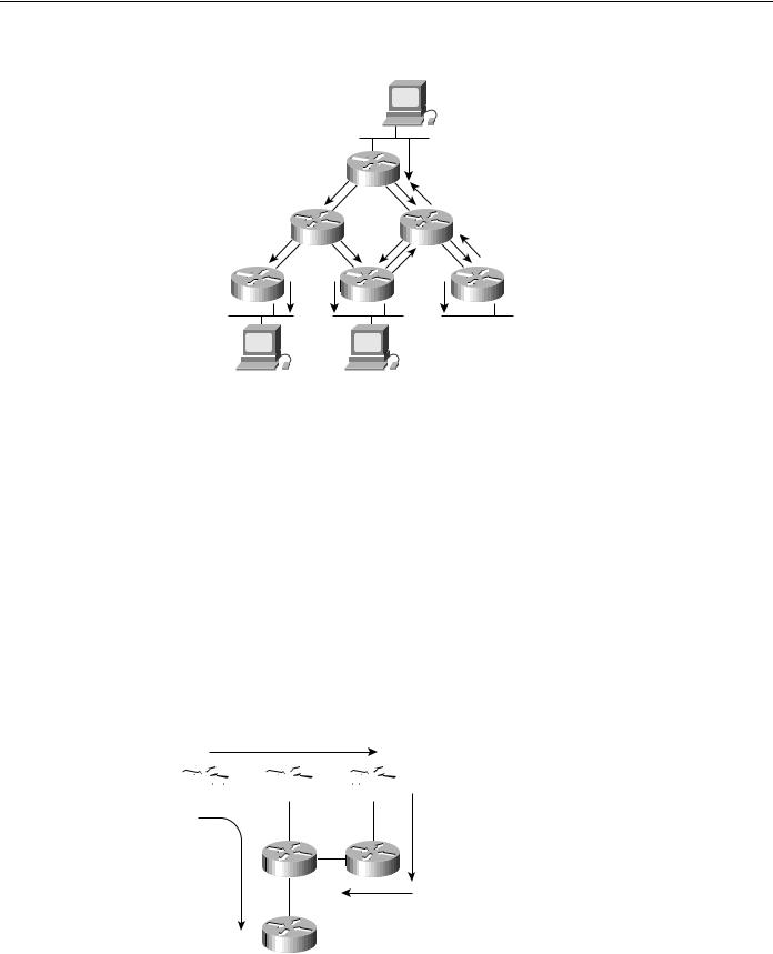
In dense mode, PIM floods the network and prunes back based on multicast group member information. Dense mode is effective, for example, in a LAN TV multicast environment because it is likely that there will be a group member on each subnet. Flooding the network is effective because little pruning is necessary. An example of PIM dense-mode operation is shown in Figure 13-15.
13-26 Cisco CCIE Fundamentals: Network Design
IP Multicast
Figure 13-15 PIM dense-mode operation.
|
Member of Group 1 |
|
Traffic |
|
Prune |
|
Prune |
|
Prune |
Member of Group 1 |
Member of Group 1 |
Sparse-mode PIM is most useful when the following conditions occur:
•
•
•
There are few receivers in a group.
Senders and receivers are separated by WAN links.
The stream of multicast traffic is intermittent.
Sparse-mode PIM is optimized for environments where there are many multipoint data streams. Each data stream goes to a relatively small number of the LANs in the internetwork. For these types of groups, reverse path forwarding would make inefficient use of the network bandwidth.
In sparse-mode, PIM assumes that no hosts want the multicast traffic unless they specifically ask for it. It works by defining a rendezvous point (RP). The RP is used by senders to a multicast group to announce their existence and by receivers of multicast packets to learn about new senders. When a sender wants to send data, it first sends the data to the RP. When a receiver wants to receive data, it registers with the RP. Once the data stream begins to flow from sender to RP to receiver, the routers in the path automatically optimize the path to remove any unnecessary hops. An example of PIM sparse-mode operation is shown in Figure 13-16.
Figure 13-16 PIM sparse-mode operation.
Data
Sender 

 Rendezvous point
Data
Optimized path
Receiver
Designing Internetworks for Multimedia 13-27

Network Designs for Multimedia Applications
Note The administrators of the MBONE plan to adopt PIM because it is more efficient than DVMRP.
Simple Multicast Routing Protocol
Simple Multicast Routing Protocol (SMRP) is a transport layer multicast protocol standard for multicast AppleTalk and IPX traffic.
Note Initial support for SMRP is provided by Cisco IOS Software Release 11.0 or later for AppleTalk only.
With SMRP, a router on each local network segment is elected as the primary node. The primary node handles requests from local devices to create multicast groups on that segment. When it wants to send multicast data, a device sends a Create Group Request packet to ask the primary node to assign a group address. The primary node responds by sending to the requesting device a Create Group Response packet that contains the assigned group address.
Devices that want to receive multicast data from this group send a Join Request packet to ask their local router to join the group. The local router forwards the Join Request to the primary node that created the group. The primary node responds by sending a Join Response.
Multicast data sent by the source is forwarded by router downstream interfaces toward receivers. Receivers can join and leave a group at any time, and a sender can delete the group at any time. The routers ensure that multicast data is transmitted as efficiently as possible, without duplication, from senders to receivers.
Routers maintain and update SMRP multicast groups by periodically sending Creator Query and Member Query packets to poll the network for the presence of senders and receivers. A router that detects the disappearance of a sender deletes the group. A router that senses the disappearance of a receiver informs its upstream neighbor to stop forwarding multicast data if no other receivers exist on the segment. Each router periodically informs its neighbors of its presence by sending Hello packets.
Network Designs for Multimedia Applications
This section examines network designs that work well with network multimedia applications. The following topics are covered:
•
•
•
Traditional LAN Designs
WAN Designs
High-Speed LAN Designs
Traditional LAN Designs
Some campus LAN environments already have adequate bandwidth for running certain network multimedia applications, but most do not. In many cases, lack of bandwidth is not caused by a slow LAN medium—instead, lack of bandwidth is caused by inefficient LAN design and segmentation.
A considerable amount of bandwidth can be gained by using switches to resegment the campus LAN environment.
13-28 Cisco CCIE Fundamentals: Network Design