

III. Дволанковий фнч на птсво
Покращення отриманих характеристик розробленого ФНЧ на ПТСВО можливо за рахунок збільшення кількості його ланок. Схемотехнічне рішення буде аналогічне до представленого, результати моделювання АЧХ одноланкового та двохланкового фільтрів при різних напругах керування (3,1 – 3,2 В) представлено на рис. 4
Рис. 4. АЧХ одноланкового та дволанкового ФНЧ на ПТСВО при напрузі керування V1=3,1 В
У двохланкового ФНЧ на ПТСВО зберігаються усі можливості одноланкового з покращеними параметрами – максимальний коефіцієнт підсилення для двохланкового ФНЧ в смузі пропускання складає 4 дБ в діапазоні (10 кГц … 1 МГц), а ослаблення поза смугою пропускання -30 дБ.
Висновок
Результати моделювання розроблених одноланкового та дволанкового ФНЧ на ПТСВО засвідчили, що використання ємнісного ефекту транзисторних структур з від’ємним опором для функціональних вузлів радіотехнічних пристроїв та радіовимірювальних приладів, дає можливість розширити робочі параметри та забезпечити їх електричне керування. Зокрема перелаштування частоти зрізу та коефіцієнтів підсилення в смузі пропускання та послаблення в смузі затримки для таких ФНЧ на ПТСВО.
Література
[1] Гуржий А. Н. Электрические и радиотехнические измерения / А. Н. Гуржий, Н. И. Поворознюк, К. : "Академия", 2004 – 272 с.
[2] Радиоизмерительная аппаратура СВЧ и КВЧ. Узловая и элементная базы / [А. М. Кудрявцев, А. Е. Львов, И. Г. Мальтер и др.] – М. : Радиотехника, 2006. – 534 с.
[3] Філинюк М. А. Основи негатроніки. Том І. Теоретичні і фізичні основи негатроніки. [Монографія] / Філинюк М. А. – Вінниця: УНІВЕРСУМ-Вінниця, 2006. – 456 с.
[4] Осадчук В. С. Фунціональні вузли радіовимірювальних приладів на основі реактивних властивостей транзисторних структур з від’ємним опором [Монографія] / В. С. Осадчук, О. В. Осадчук, А. О. Семенов, К. О. Коваль – Вінниця: УНІВЕРСУМ–Вінниця, 2011. – 336 с.
Високо-частотний зв'язок – ефективне рішення для сучасних комунікаційний систем
Шимон Панеский
Кафедра Елекроніки, Вроцлавський Університет Технології, ПОЛЬЩА, Вроцлав, вул. Вибжече Виспянскєго 27, E-mail: szymon.panecki@pwr.wroc.pl
Концепція комунікативної системи заснованої на лініях електропередач (відомі як PLC - Power Line Communication (високочастотний зв'язок по лінії передач)) є широковідомою протягом багатьох років. Перші спроби застосування цієї технології були зроблені в першій половині минулого століття. Проте, через чисельні проблеми, причиною яких був недостатній рівень розвинутості науки, ця концепція не могла бути використаною на масштабному рівні в минулому. Тепер, після багатьох років досліджень та проведених покращень, ця технологія стає вагомою альтернативою у порівнянні з існуючими системами трансмісії. Динамічний зріст цієї альтернативи можна спостерігати останнім часом, через те, що велика кількість існуючих електричний мереж дозволяє використовувати високочастотний зв'язок у багатьох телекомунікаційних послугах, таких як доступ до Інтернету чи цифрова телефонія. Засоби комунікації для технологій з вико частотним зв’язком по лініям електропередач вже існують у більшості видів застосування (як машини чи будинки), тому найбільшими перевагами цієї технології є зменшення кількості дротів та коштів, які вимагаються для встановлення. Ці переваги роблять дану технологію привабливим рішенням для індустріальних мереж. Цей аргумент змушує ближче придивитись до стандарту високочастотного зв’язку по лініям електропередач та зробити спробу розробити проекти засновані на цій технології.
В цій статті автор пропонує просту комунікативну систему засновану на технології передачі високих частот. Топологічна схема системи є шинною топологією. Основна функціональна одиниця системи є мережевий режим. Це є прилад, який дозволяє отримувати та передавати дані через мережу. Автор пропонує структурну модель мережевого вузла та побудову двох вузлів, які є засновані на цій моделі та складаються з електронних компонентів, які є доступними на ринку. Внаслідок автор оснащує перший вузол датчиками вологості\температури та другий вузол оснащує рідкокристалевим екраном (LCD display) та створює просту систему високочастотного зв’язку (PLC system).
Переклад зроблено Горьковою Н.Г., центр іноземних мов «Universal Talk», www.utalk.com.ua
Power Line Communication – efficient solution for modern communications systems
Szymon Panecki
Department of Electronics, Wroclaw University of Technology, POLAND, Wroclaw, Wybrzeże Wyspiańskiego street 27, E-mail: szymon.panecki@pwr.wroc.pl
The concept of communication system based on power lines (known as a PLC - Power Line Communication) is widely known for many years. The first attempts of implementation of this technology were taken in the first half of last century. However, because of the many problems resulting from insufficient level of science, this concept could not be used on a massive scale in paste. Now, after many years of research and made improvements, this technology became a viable alternative to existing transmission systems. Its dynamic development can be seen particularly in recent times, because big amount of existing electricity networks allows to use PLC in many telecommunication services such as Internet access or digital telephony. Communisation medium for PLC technology already exists in most applications (like cars or buildings), so the biggest advantages of this technology are reduction of wires and costs required for its implementation. These advantages make this technology an attractive solution for industrial networks. This argument encourages to have a closer look at the PLC standard and make an attempt to design projects based on it. In this article author will propose a simple communication system based on PLC technology.
Кеуwords – Power Line Communicationc, PLC, network, system, microcontroller.
I.The concept of PLC system
The aim of this project was to design and build a simple PLC system. Such system should be understood as a transmission medium (power lines int this case) and group of electronics devices connected to each other by transmission medium. Rules of communication in each system is strictly defined by a set of rules, which can be called as architecture. Architecture is a factor, which determines whole system, because it defines network topology, transmission protocol and other communication issues.
The most important architecture aspect, which should be defined, is a network topology, because it has big influence for all other factors. Topology, which was approved for prpoposed solution is a bus topology. This topology is characterized by the fact, that all network devices (called as nodes) are connected to transmission lines, which are shared by all nodes. This network topology allows only one transmission at a time. Information sent by one of the nodes is received by all others, but only node to which the information was addressed, interprets it. The structure of the PLC network model with a bus topology is shown in Figure 1.
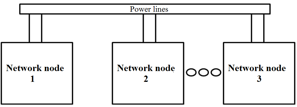
Fig.1 PLC system based on bus topology
II. The concepto of PLC network node
The basic functional unit of a system is a network node. It is a device, which allows receiving and transmiting of data through the network. The structure of the network node with functionality allowing shared use of power lines as a medium for data transmission/reception in the most general form can be reduced to three elements (Figure 2).
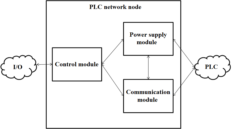
Fig.2. Block diagram of PLC Network node
This structure includes:
• communication module,
• control module,
• power supply module.
Communication module is responsible for the entire process associated with data transmission (sending and receiving of information). Data on PLC bus have an analog form and communication inside each node is in digital form, so communication module has to convert signals. After receiving of the PLC frame, communication module converts it to digital form and sends it to the control module. The opposite situation is similar – after receiving data from control module, communication module converts it to analog form and sends it by power lines to the rest of the nodes.
The task of the control module includes execution functions. It performs configuration of whole node, interpretation of frames received by the communication module, decision when to send frames and with which data and address. This module also performs communication with peripheral devices (such as sensors, displays, memory and others).
The last module (power supply module) is responsible for supplying power to other modules, which allows them to work correctly. This is done by converting the available voltage from power lines to the level required by the communication module and control module.
III.Selection of components for network node
For each of the modules author selected appropriate electronic components. The first module, which will be discussed, is a control module. The control module consists of a microcontroller and some peripheral components (resistors, capacitors), which ensure its proper operation. Microcontroller, which was chosen for this project is a STMicroelectronics STM32F103C8T6 based on ARM Cortex-M3 core. This microcontroller ensures high performance (clock can be tuned up to 72 MHz) and versatility because of its embedded resources (large amount of internal memory, multiple communication interfaces). The full specification of the STM32F103C8T6 microcontroller is shown In Table 1.
TABLE 1
Specifications of STM32F103C8T6 microprocessor
Supply voltage level |
2.0 – 3.6 V |
Frequency |
up to 72 MHz |
FLASH memory |
64 kB |
SRAM memory |
20 kB |
Timers |
three universal 16-bit, two Watchdogs, 24-bit system timer |
Analog to digital converter |
two 12-bit |
Communication interfaces |
USB (1), CAN (1), USART (3), I2C (2), SPI (2) |
Operating temperature |
–40 to + 125 °C |
Package |
LQFP48 |
Another element of device is a communication module. Its main component is the transmission circuit. Its choice has a fundamental importance, because it is a circuit greatly influencing on functionality of the device. For this project author decided to use SIG60 transmission circuit developed by Yamar Electronics. The most important technical data of SIG60 circuit are shown in Table 2.
TABLE 2
The most important technical data of SIG60 circuit
Supply voltage |
3.0…3.6 V |
Communication interface |
UART (9600 bps … 115200 bps) |
PLC Signac frequency |
1.75 MHz, 4.5 MHz, 5.5 MHz, 6 MHz, 6,5 MHz, 10.5 MHz, 13 MHz |
Current consumption:
|
40 mA 50 mA 80 uA |
Operatinf temperature |
–40…+ 125 °C |
Package |
QFN28 |
Yamar Electronics company, to help users to get started with its products and shorten the construction time for devices based on them, prepared evaluation kits with SIG60 circuits. They allow to use the full functionality of SIG60 circuits and are intended for both prototype and final applications. Yamar SIG60 kits are able to transmit and receive data using 12 V (DC) voltage. In proposed PLC node author used such kits.
The last of the modules, which is a part of network node, is a power supply module. Fortunately in this case there is no need to design this module, because it is possible to use the power supply circuit integrated in the SIG60 kit. Kit’s supply block SIG60 consists of a voltage converter circuit, that converts the voltage level available on the power lines to the level of 3.3 V, which is required by the SIG60 circuit. 3.3 V output voltage is available on the SIG60 signal connector, so it can be successfully used to power other components of the node, including microcontroller. This allows to threat SIG60 power block as a power supply module for the entire node.
IV. Desingning and building of the node
According to the adopted concept of the construction of the device, it consists of three modules: control module, communication module and power supply module. Control module is based on STM32F103C8T6 microcontroller with some additional peripheral components. Communication module is based on Yamar SIG60 kit, which thanks to the integrated power supply can also act as a power supply module. At first author created a wiring schematics, which includes all these components connected to each other in accordance with application notes and datasheets. Then author designed a PCB board, which was based on the wiring schematics. The project board has been optimized to have a small dimensions. Therefore it was decided to use mainly the elements in SMD packages and place them close to each other, which greatly contributed to the small surface of the PCB (90 mm x 39 mm). Miniaturization did not increase the complexity of the PCB, so most of the signal lines are on one side of PCB. Full layout of the PLC network node is shown in Figure 3.
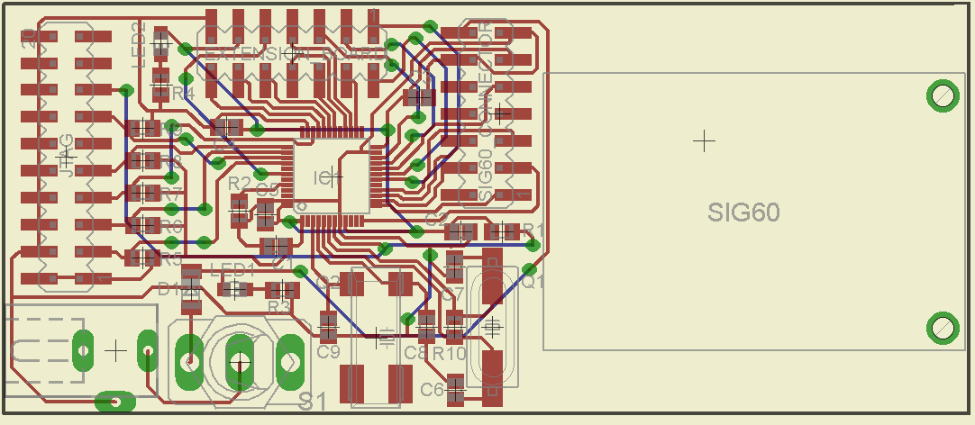
Fig.3 Layout of the PLC network node
Photo of built PLC network node is show in Figure 4.

Fig.4 Photo of PLC network node
V. PLC system based on the network nodes
High functionality of PLC nodes allows to use them for a variety of applications requiring PLC data transmission. Example application will be presented. It is a simple sensor network, which consist of two nodes. The first node was equipped with Sensirion SHT11 temperature and humidity sensor, while the second node was equipped with Electronic Assembly DOGM128 LCD display. This configuration of the system allowed to use node 1 as an instrument for acquiring measurements of environmental parameters in a designated area. After each measurement, node sends its value by a 12V voltage lines to the remote node number 2, which visualizes the measurements on the LCD. Schematic diagram of the system is shown in Figure 5.
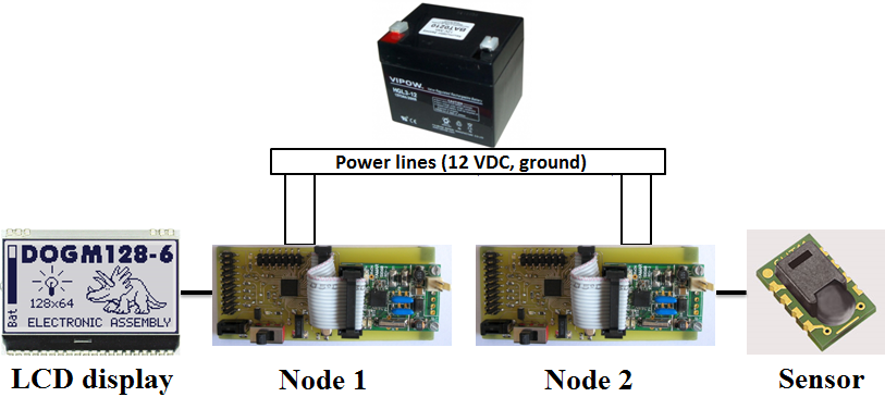
Fig.5 Structure of PLC example application using PLC network nodes
Photo of this PLC system is show in Figure 6.
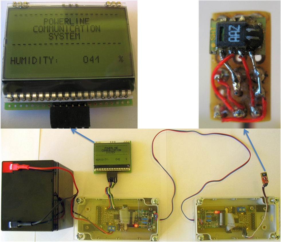
Fig.6 Photo of PLC system, which is a simple sensor network
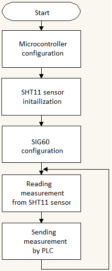
Fig.7 Block diagram of the transmitting node’s program
This is a very simple example of the communication system, because it not only consists of a minimum number of nodes (only two), but also the communication takes place in its simplest form, so only in one direction (node number one sends data, mode number two receives data). The advantage of such structure is no need of implementation of the mechanism allowing access to the medium.
Block diagram of the transmitting node’s program is shown in Figure 7. It includes the configuration of the microcontroller, initialization of the SHT11 sensor, configuration of SIG60 module, then a cyclic reading of the sensor measurements and sending them through the power supply lines.
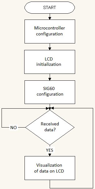
Fig.8 Block diagram of the receiving node’s program
Now source code of receiving node will be discussed. A significant piece of code of receiving node is the same as in transmitting node. Common to both nodes is configuration of the microcontroller and SIG60 module. New element in receiving node is a LCD display. The full block diagram of the receiving node’s program is shown in Figure 8.
Conclusion
PLC is a very promising technology, which develops quickly nowadays. This technology progress allows to use PLC in existing and new applications, which require using data communication. Areas, where PLC is used more and more often is for example automotive industry and home automation systems. Successful implementation of author’s PLC system confirms advantages and big potential of this technology.
References
[1] P. Borkowski, "AVR i ARM7. Programowanie mikrokontrolerów dla każdego", Helion, 2010.
[2] Y. Maryanka, "Wiring Reduction by Battery Power Line Communication", May 2010.
[3] K. Paprocki, "Mikrokontrolery STM32 w praktyce", BTC, 2009.
[4] N. Pavlidou, A. Vinck, J. Yazdani, B. Honary, "Power Line Communications: State of the Art And Future Trends", April 2003.
[5] J. Yiu, "The definitive guide to the ARM Cortex-M3", Elsevier Science, 2007
[6] www.yamar.com "SIG60 Module Manual", 2009.
[7] www.yamar.com "SIG60 – UART over Powerline for AC/DC-BUS Network", 2009.