

|
|
|
Waste sources and classification |
|
17 |
|
Table 2.3 |
|
|
|
|
|
|
(Continued ) |
|
|
|
|
|
|
|
|
|
|
|
|
|
Nuclide |
Half-life (y) |
Dec. |
Nuclide type |
Produced |
Percentage |
Relevance |
|
|
|
|
from |
of total |
|
|
|
|
|
|
or activity |
|
|
|
|
|
|
in spent |
|
|
|
|
|
|
fuel (40y) |
|
|
|
|
|
|
|
|
Pu-241 |
14.4 |
|
AC |
|
11.2 ( ) |
criticality |
Pu-242 |
3.8Eþ05 |
|
AC |
|
|
|
Am-241 |
432 |
|
AC |
Pu-240 |
43.0 ( ) |
heat output |
Am-242m |
141 |
|
AC |
Am-241 |
|
|
Am-243 |
7370 |
|
AC |
Am-241 |
|
|
Cm-242 |
0.45 |
|
AC |
|
|
n-dose rate |
Cm-243 |
29.1 |
|
AC |
|
|
|
Cm-244 |
18.1 |
|
AC |
|
11.5 ( ) |
n-dose |
|
|
|
|
|
|
rate, heat |
|
|
|
|
|
|
output |
Cm-245 |
8500 |
|
AC |
Pu-239 |
|
|
Cm-246 |
4730 |
|
AC |
|
|
|
|
|
|
|
|
|
|
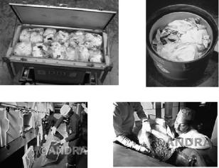
Fig. 2.6. Typical wastes from reactor operations (image courtesy of ANDRA).
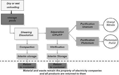
2.4.1.4. Reprocessing
A SF assembly essentially consists of a large number of long rods (containing the spent fuel pellets), which are held in place by grids and relatively large metallic end and bottom pieces. The objective of reprocessing is to separate the fission and transuranic elements (4 per cent) from the uranium (95 per cent) and plutonium (1 per cent) contained within the spent fuel pellets (Fig. 2.7). In relation to the 25 tonnes of fuel mentioned above, reprocessing would result in 1 tonne of fission products and transuranics, 23.75 tonnes of uranium and 0.25 tonnes of plutonium.
18 |
D.F. McGinnes |
Fig. 2.7. A simplified overview of the reprocessing process (image courtesy of AREVA-NC).
The commercial process basically consists of chopping the fuel rods into small pieces and dissolving the fuel pellets in concentrated nitric acid. The liquid containing the waste fission products and transuranics is then separated from the uranium and plutonium. Following this, the uranium and plutonium are then separated from each other, purified and re-used. The high-level waste liquid containing the fission products and actinide (both transuranics and residual uranium and plutonium) isotopes is dried by a calcination process to produce a solid which is then mixed with borosilicate glass and vitrified. The resulting glass is then cast into stainless steel containers and stored. For geological disposal, it is envisaged that each of these containers will be separately placed in a massive metal container (overpack) (e.g., steel in the Swiss and Japanese concepts (Nagra, 1985; JNC, 2000), copper in the Swedish (Werme, 1998) and Finnish (Raiko and Salo, 1999) concepts – see also Chapter 5 for further details).
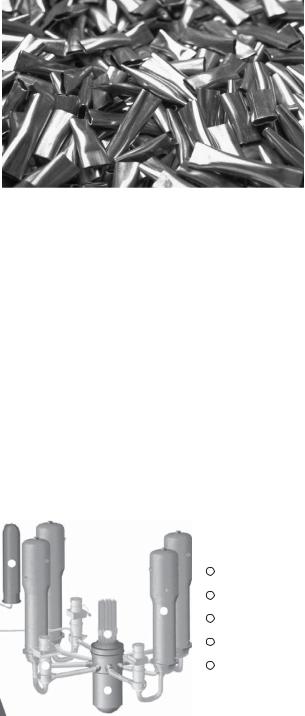
After dissolution of the spent fuel, the remaining fuel structural materials (Fig. 2.8) and heavily contaminated materials (such as pumps, clothing, etc.) and process residues (effluent treatment) are conditioned as L/ILW-LL. Other wastes, such as lightly contaminated materials, are conditioned and disposed of as L/ILW-SL.
2.4.1.5. Reactor decommissioning
On closure of nuclear facilities, the buildings are generally decontaminated and dismantled. In the case of NPPs, the first stage of decommissioning consists of the removal of all of the SF, accounting for 99 per cent of the radioactivity, from the facility. This then allows the facility to move from an operating to a decommissioning licence. Following this, the reactor (Fig. 2.9) is then completely dismantled to a greenfield site (with no conditions on its subsequent use), with the number of stages and the amount of time required to reach this final stage being dependent on the approved strategy.
Waste sources and classification |
19 |
Fig. 2.8. Reprocessing waste – LILW-LL hulls (image courtesy of AREVA-NC).
The majority of radioactive waste generated from decommissioning activities arises from contaminated or activated components and is conditioned as L/ILW-SL. Depending on national regulations and initial impurity levels (especially uranium and thorium), some of the reactor core components may be classified as L/ILW-LL. A large amount of the waste from the decommissioning of nuclear facilities is generated from the dismantling of support buildings that are not exposed to radiation or any radioactive material, such as office buildings. These facilities can be decommissioned using conventional techniques and the resulting waste can either be recycled or disposed of at a conventional landfill site.
A modern light water reactor would be expected to produce 10 t of decommissioning waste per MW(e) of installed capacity, which equates to around 10,000 t of waste in the 1 GW(e) case (NEA, 2003).
PWR reactor coolant system and its main components
5
1 Reactor vessel
2 Control rod drive mechanisms
3
3 Steam generator
2
4 Reactor coolant pump
4 |
5 Pressurizer |
1
Fig. 2.9. (Continued)
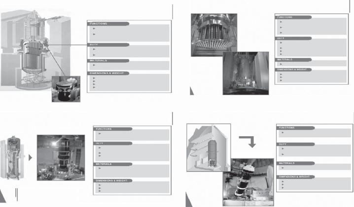
PWR reactor pressure vessel (and equipments)
to hold the reactor core and the surrounding structures
to withstand the hight presure
(155 bar) of the core collant circulating water (around 300°c)
nominal and transient pressures and temperatures
neutron irradiation
low alloy Carbon steel with a stainless steel layer inside
height:12 to 13 meters
internal diameter: 4 to 4.5 meters thickness: 13 to 20 centimeters weight: 330 to 460 metric tons
PWR pressure vessel internals
to support and maintain laterally the fuel
assemblies
to guide the control rods and the internal
instrumentation
to distribute the coolant flow within the core
mechanical effects of the coolant flow
circulation
chemical effect of the collant fluid irradiation
nominal and transient temperatures
stainless steel and Nickel based alloys
height: 12 to 13 meters diameter: 4 to 4.5 meters weight: 160 to 230 metric tons
Design Commissioning
Heat transfer surface: 4,700 to 7,000
square meters
PWR steam generator |
Pressurizer |
|
Design |
to transfer heat and ensure leak-tightness between the primary (P) and secondary (S) circuits
mechanical effects of the circulating P and S flows
chemical effects of the P and S fluids nominal and transient temperatures and pressures on P and S sides
Nickel based alloy (tubes),
low internal alloy Carbon steel (structures) with a stainless steel layer the water chamber (P side)
height: 20 to 22 meters diameter: 3.5 to 5 meters
weight (empty): 300 to 420 metric tons
Commissioning
to maintain constant the pressure in the reactor coolant system
nominal and transient temperatures and pressures
chemical effects of the primary fluid
low alloy Carbon steel
height: 13 meters diameter: 2.5 to 3 meters
weight (empty(: 70 to 120 metric tons
20
McGinnes .F.D
Fig. 2.9. Main components of a pressurised water reactor (PWR) (image courtesy of AREVA-NC).