

Repository design |
137 |
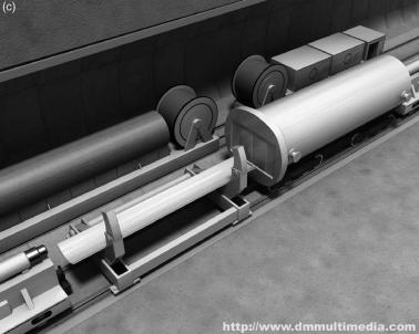
Fig. 5.8. An example of tele-handling of a HLW canister – transferral from the rail transporter to the canister support in the repository (images courtesy of DMMultimedia). (a) Following transport to the repository (by rail, in this example), the heavily shielded transport flask (right) is placed in the package transfer zone (in this example, underground). From this point on, all handling must be carried out remotely due to the high activity of the waste. The waste canister is pushed out of the transport flask (right) onto the handling apparatus (centre) by means of a hydraulic ram (not shown). (b) The handling apparatus slowly swings the canister across to the bentonite/sand canister support (rear), which is already loaded onto the underground transport carriage. (c) Once securely on the canister support, the electric shunter (top right) can transport the canister and support (as one package) into the repository tunnels for final emplacement.
5.6. Future perspectives
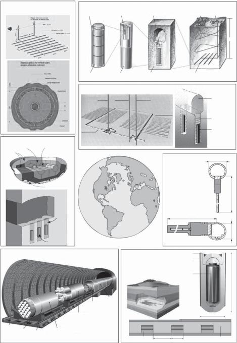
As noted previously, the long-term safety of a repository is assured by a combination of engineered and natural geological barriers. Studies carried out over the last couple of decades have shown that, under the boundary conditions set by various national programmes, many different combinations of waste type/engineered structures and geological settings can provide high levels of safety (for some examples, see Figure 5.9). The characteristics of EBS materials and alternatives are generally extensively reported in each national programme and their behaviour and evolution with time are well supported by extensive laboratory studies, mechanistic modelling and natural analogue studies. An area which is less well defined, however, is the practicality of construction of such an EBS under strict QA controls in an operational repository environment (considering underground conditions of restricted space, humidity, emplacement rate, tele-(robotic) handling of highly active waste, operational safety, robustness to perturbations, etc.). In addition to these primary engineered barriers, a number of other repository structures may have
138 H. Umeki
Belgium |
Sweden |
(courtesy of SKB) |
|
|||
(courtesy of ONDRAF/NIRAS) |
|
|||||
Cladding tube |
Spent nuclear fuel |
Bentonite clay |
Surface portion of deep repository |
|||
|
||||||
|
|
|
|
|
500 m |
|
|
Fuel pellet of |
Copper canister |
|
Crystalline |
Underground portion of |
|
|
uranium dioxide |
with cast iron insert |
bedrock |
deep repository |
||
|
Finland |
(courtesy of Posiva) |
|
|||
|
Work shaft |
Personnel shaft |
Canistar transfer shaft |
Tunnel backfill |
||
|
|
|
|
Disposal tunnels |
|
|
|
|
|
|
|
Bentonite |
|
|
Central tunnel |
|
|
|
Metal canister |
|
Canada (courtesy of OPG)
Copper
Buffer Container
Backfill
Concrete
Backfill
Buffer
Titanium
Container
France 5.00m
(courtesy of ANDRA)
19.50m
23m
4.80m
USA (courtesy of U.S. DOE) |
Switzerland |
Welding seam
Canister lid
|
|
|
|
|
|
(courtesy of Nagra) |
|
|
|
|
|
|
|
|
|
|
|
Stainless steel |
|
|
|
|
|
|
|
|
|
flask with HLW |
|
|
|
|
|
|
|
|
|
glass |
|
|
|
|
|
|
|
|
|
|
2 m |
|
|
|
|
|
Drip |
|
|
|
|
|
|
|
|
Boiling Water |
Shield |
|
|
|
|
|
|
|
|
|
|
|
|
|
|
|
|
|
|
Reactor Waste |
|
|
|
|
|
|
|
|
|
Package |
|
|
|
|
|
|
|
|
|
Codisposal Waste |
|
|
|
|
0.94 m |
|
|
|
|
Package Containing |
|
|
|
|
|
|
|
|
|
|
|
|
|
|
|
|
|
|
|
Five High-Level Waste |
|
|
|
|
|
|
|
|
|
Canisters with |
|
|
|
|
|
Steel Sets |
|
|
|
One DOE Spent |
|
|
|
|
|
|
|
Pressurized Water |
Nuclear Fuel |
|
|
|
|
|
|
for Ground |
Steel |
|
|
|
|
|
|
||
Control |
Invert |
Gantry |
Reactor Waste |
Canister |
|
|
|
|
|
|
Structure |
Crane Rail |
Package |
Drawing Not to Scale |
|
3 m |
2 m |
|
|
|
|
|
|
Bentonite blocks |
Bentonite pellets |
||||
|
|
|
|
00022DC_ATP_Z1530-02n.al |
(compacted) |
|
|
|
|
Fig. 5.9. Repository design variants considered in feasibility studies by different national programmes (ANDRA, 2001; Gierszewski et al., 2001; Nagra, 2002; ONDRAF, 2001a,b; Posiva, 1999; SKB, 2001; U.S. DOE, 2002). These options are not yet finalised and may be modified significantly before the repositories are implemented.
Repository design |
139 |
barrier roles – e.g., tunnel liners, borehole caps, backfilling, plugs and seals for tunnels, ramps and shafts. As yet, the performances of such structures and their possible interactions with each other (and the primary EBS) have not been examined at a detailed level.
Studies have been initiated to develop alternative repository design concepts (SKB, 1992; Lindgren, 2003; NUMO, 2004), which increase flexibility in design, given potential constraints from the siting environment and/or social requirements. In the NUMO study in particular, a range of potential design options have been investigated and the various components of the repository have been catalogued for developing repository concepts for the volunteer approach to site selection (see also Chapter 9).
For the case where very compact repository designs like those described previously are under consideration, it becomes feasible to consider an alternative approach to respond to relatively high water flows – by engineering improvements to the rock surrounding the repository. An obvious approach for a multi-level repository with external spiral access ramps would be to use existing grouting technology to reduce rock permeability – in effect forming a hydraulic barrier around the entire emplacement zone. Such a barrier could considerably reduce water inflow into the repository during the operational (and any post-operational, institutional control) phase. Reduced inflow not only makes drainage easier (considering both expected operation and perturbations such as power cuts), but reduces the perturbation of the local groundwater system which could be caused by decades of such drainage – e.g., forming a drawdown cone which could bring oxidising, surface waters to the emplacement levels with consequent geochemical alterations of the ambient rocks. The extent to which such a barrier could also perform a role over a longer term following repository closure is difficult to assess at present but, at least in principle, this would be possible.
An alternative way to reduce flow through the repository would involve construction of a high permeability ‘‘hydraulic cage’’ around the repository – similar, in principle, to the Swedish ‘‘WP Cave’’ concept (e.g., SKB, 1992).
Although perhaps counter-intuitive, such a very high permeability structure diverts flow around the repository in a manner analogous to the function of the high electrical conductivity ‘‘Faraday cage’’ for electromagnetic radiation. This approach is not practically applicable to rocks with a generally high permeability, but could be useful in cases where a high water flux is caused by a high hydraulic gradient or cases where low water flux is associated with high water velocities due to localisation of flow (e.g., in a network of fractures). This option may increase the local hydraulic perturbation during the operational phase, but could well significantly improve long-term repository performance (as the long lifetime of a high-permeability zone may be easier to assure than that of a low-permeability zone).
For sites where the available area of suitable host rock is limited (by either geological or political constraints), multi-level emplacement panel designs can be considered. For a rock with good mechanical properties, 5–10 emplacement levels could be considered within the boundaries set by the minimum repository depth (often set by law) and the maximum depth of around 1000 m, often determined by the geothermal gradient (as operations become much more complicated if ambient rock temperatures are significantly above 50–60LC). A particular concern which has to be addressed with such options is thermal loading, which can result in temperatures within the bentonite buffer rising above chosen limits. There is, indeed, much evidence that even decades of exposure to temperatures up to 150LC cause no significant degradation of the
140 |
H. Umeki |
properties of compacted bentonite/sand buffer (Miller et al., 2000) and hence confirmation of this could be a focus for supporting R&D if such an option was under consideration. Alternatively, a prefabricated EBS module design could be produced, in which the integrity of the external handling shell (NUMO, 2004) is assumed over the critical thermal period (as no alteration of dry buffer would occur). Indeed, such prefabricated modules offer many practical advantages in terms of remote handling, emplacement QA, layout flexibility, etc. and merit more detailed study of the range of designs which could be considered. Delayed backfilling of the repository based on the cavern retrievable concept (Masuda et al., 2004) is another option.
Special challenges arise for cases in which a particular site may be suitable in terms of geological stability, but contain host rocks of relatively high permeability. Although such permeability may lie in a range that is not critical for long-term safety (as hydraulic gradients may be very low in deep geological environments), inflow of water could present particular difficulties for some disposal options. Nevertheless, low-permeability liners and/or prefabricated EBS modules could be used to design a feasible system.
The same basic concept of borehole emplacement can be utilised for horizontal/subhorizontal emplacement in locations where more conventional repository operational schemes may be difficult – e.g., in relatively weak rocks in a coastal location. Again, consideration of practicality of emplacement leads to focusing on prefabricated EBS designs.
Given the high weighting assigned to public acceptance, it might well be necessary (or desirable) to move away from the fundamental disposal philosophy behind the examples illustrated above. These concepts are all based on the idea that waste is sealed in place as quickly as possible – for the very good reason that a sealed disposal system is inherently more stable mechanically, hydrologically and geochemically. Any ‘‘monitoring’’ which is included in such designs must avoid perturbing the engineered barriers and hence, with present technology, cannot really measure any parameter relevant to long-term safety.
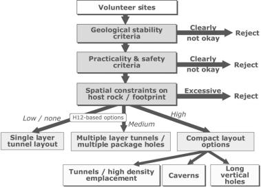
Fig. 5.10. Illustration of evaluation of constraints on a site and resultant design variants (NUMO, 2004).