

Repository design |
131 |
The selected EBS is specified for a basic repository concept, which, in turn, is iteratively refined to specify logistics and infrastructure, including:
Shafts and/or ramps to provide access to the host formation for personnel and materials and for removal of broken-out rock. Additional requirements for ventilation, emergency escape routes, etc. are defined by normal mining regulations but may be redesigned based on assessment of operational phase radiological safety.
Tunnels and drifts for internal transportation of materials and services – possibly allowing separate construction and operation of different parts of the repository. Layout is specified by constraints set by the local geology (major structural features, stress fields, hydraulic gradients, etc.) and practical aspects of repository operation.
Emplacement tunnels or boreholes in a specified region (or regions/panels) of the repository. These are designed to be compatible with performance and quality assurance requirements.
Structures for backfilling and sealing the repository – including tunnel and shaft seals and plugs – optimised for the layout/host rock in question and demonstrated to provide the roles specified in the long-term performance assessment.
The depth range for practical construction of the disposal facility is determined by evaluating the mechanical stability and spatial extent of the host rock. Mechanical stability analyses support the prediction that, for hard rock, underground excavations would be stable without supports at greater depths. For soft rock, when the viability of realistic supports is taken into consideration, tunnels could reasonably be constructed at a depth greater than a few hundred metres.
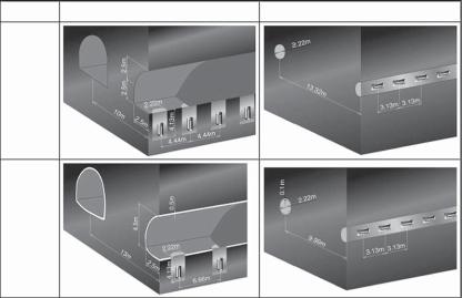
For HLW/SF, the scale of the underground facilities can be estimated approximately by multiplying the occupied area per waste package (given by the product of the disposal tunnel spacing and the waste package pitch) by the number of waste packages. A combination of the disposal tunnel spacing and waste package pitch should be specified such that the scale of the underground facilities and the total length of disposal tunnels will be reduced, thereby improving economic factors. To specify the disposal tunnel spacing and the waste package pitch, consideration should also be given to the thermal effects of waste on the EBS, in addition to the constraints due to the mechanical stability. An example of resulting disposal tunnel spacing and the waste package pitch for which the maximum temperature of buffer material would be below the constraint temperature (100LC in this particular design) is shown in Figure 5.7 (JNC, 2000).
The cross-section of a disposal tunnel and the spacing between tunnels can be designed based on mechanical stability for non-heat-generating, cementitious/bituminised L/ILW. The disposal tunnels for the hulls and ends would obviously be located so as to avoid any thermal effects on the cement-based materials.
5.5. Design confirmation and demonstration
5.5.1. Interaction with PA/SA
While the main safety functions of the repository are intrinsic to the design and location within a deep geological system, understanding the level of robustness of the proposed
132 |
H. Umeki |
Pit disposal |
Tunnel disposal |
Hard rock
Soft rock
Fig. 5.7. The EBS concept for the in-hole and in-tunnel disposal options for different types of host rock (JNC, 2000). Waste package dimensions and buffer thickness are the same for the in-hole and in-tunnel disposal options. In this PA, these options were considered to be equivalent. This assumption was based on a lack of consideration of either the emplacement hole plug or the excavation disturbed zone (EDZ) of the large tunnel or the deposition hole.
system in various geological conditions or under changes in system conditions can only be evaluated through long-term repository performance assessment. Ideally, over time, the iterative process of PA and repository design work should lead to a situation where the design has matured and become stable (relatively unchanging with each new iteration) and is consistent with the PA models. The same iterative process should lead to mature PA models that provide a reasonable (not overly simplified) representation of the disposal system. The general approach and methods for PA/SA have been developed to evaluate the safety functions and the level of robustness of the proposed system under various conditions (see Chapter 6). Results of PA/SA can be fed back to design confirmation or further modifications.
The behaviour of the EBS and the evolution of the near-field of a repository are critically dependent on the local-scale properties of the host rock and on the larger scale features of the surrounding geological environment. For many geological environments being considered for disposal, groundwater flow and chemistry will be significant factors affecting near-field performance. For example, according to McKinley (1985), based on the known potassium content of the groundwaters and the likely flux of water through the EBS, illitisation of bentonite in a HLW/SF repository in the crystalline basement of northern Switzerland would take about 1 million years at one site (west) and as much as 10 million years at another site (east).
As discussed previously, throughout the construction, operation and closure of the repository a sequence of various processes and events take place in one part or another, resulting in a dynamic evolution of the facility and its environment. Materials and equipment of many kinds are introduced underground for the sake of operational safety
Repository design |
133 |
and engineering efficiency. Furthermore, perturbations to the environment during construction and operation, together with the materials left after the closure of the repository, could affect the further evolution of the system and thereby affect near-field conditions that are of vital importance in assuring long-term safety. Evolution of the near-field environment should be attributed to a number of THMC processes and their mutual interactions, rather than being governed by a dominant process.
Coupling of processes is particularly important in the description and modelling of the near-field barriers. The temperature rise within the repository is a critical factor for a range of possible processes. Effects include the stress distribution within engineered barriers and the host rock. Additional phenomena that can be affected are the flow of fluids and biological activity, together with the physico-chemical and thermodynamic conditions. While coupling of processes is particularly important in the description and modelling of the near-field barriers, consideration of their potential impact will also be necessary in the far-field. A good understanding of such coupling of processes is essential for the reliable assessment of repository performance and for the production of a convincing safety case. In this context, a coupled THMC model has been developed as part of international projects such as DECOVALEX (Jing et al., 1996) and FEBEX (ENRESA, 2000). Along with these projects, coupled THMC tests, conducted on engineering scale or full scale, have been carried out to investigate the validity of the developed models (codes).
Analyses are performed to evaluate the long-term integrity of the EBS to confirm its performance after emplacement. These include an evaluation of the long-term structural mechanical stability of the EBS based on consideration of rock creep and the expansion of container corrosion products, the seismic stability of the EBS and the near-field, the EBS behaviour during resaturation and potential gas formation and migration through the EBS. Most systems would maintain integrity against expected phenomena over a long period of time (JNC, 2000).
The EBS within the near-field is intended to contain the radionuclides in the wastes completely for a certain period of time and then to control the rate at which they can be mobilised and released into the surrounding rock. The results from radionuclide release and transport calculations could be used as input to studies aimed at optimising the design and layout of the repository and the EBS. To do this, the radionuclide release and transport calculations are likely to need to be supported by a detailed model of groundwater flow around the repository, so that significant flowpaths can be identified. The importance of results from radionuclide release and transport calculations for optimisation studies would also depend on the relative significance of the far-field in the performance of the disposal system under consideration.
5.5.2. Demonstration and QA
Demonstration of technical reliability rests on two fundamental principles. First, that a properly sited and designed repository with a robust EBS is intrinsically safe because it avoids potential major disruptive processes and ensures that any releases of radionuclides in the far future will have no significant health effects. The second principle is that a PA of the engineered and natural barrier system can demonstrate a wide margin of safety for the proposed disposal concept.
134 |
H. Umeki |
An area that is less well defined, however, is the practicality of constructing an EBS under strict quality assurance controls in an operational repository environment (considering underground conditions of restricted space, humidity, emplacement rate, remote handling, operational safety, robustness to perturbations, etc.). Remaining design uncertainties relate mainly to issues of how to link EBS design and emplacement methods to disposal system performance. Key characterisation uncertainties include the THMC properties of buffer and backfill materials and the evolution of those properties, the effect of gas generation and the determination of parameter values for safety analysis.
Many programmes are actively involved in experiments in URLs. This is an area of extensive international collaboration and there are clear links between URL experiments, laboratory experiments, natural analogues, process modelling and data gathering. As noted in Chapter 8, some programmes include URL experiments in an iterative process of PA and design refinement. The objectives of the URL experiments are to demonstrate the function of deep repository components under realistic conditions and compare results with models and assumptions and to develop, test and demonstrate engineering standards and quality assurance methods.
Peer review is an important positive process that enhances confidence and should be an active part of the ongoing design and assessment process. Issues identified through peer reviews in different countries include the need for:
Demonstration of technical feasibility.
Further R&D on particular topics.
Balance between EBS and natural barriers.
Consideration of uncertainties in expected performance.
5.5.3. Repository management
The management of a disposal site covers all operations for constructing, operating and decommissioning the repository, including gathering the technical information necessary to support a decision to release the site from institutional control.
The process for implementation of geological disposal begins with selection of potential candidate sites, selection of candidate sites and characterisation of the candidate site(s), followed by demonstration of disposal technology, disposal facility design and safety assessment. Confirmation by the regulator of the selection of potential candidate sites is required. An application for regulatory approval is then submitted and, provided a safety review ultimately determines that the proposed site is suitable, the repository project will be granted an official permit. Operations to be conducted at the disposal site will be carried out in three stages of construction, operation and closure; a key decision will be the extent to which such operations proceed in parallel in different parts of the repository.
In each phase of work, consideration should be given to the following aspects of management of a disposal site:
Implementation of quality control for design, manufacturing, installation and construction of the EBS and the disposal facility (as specified in the previous section). Quality management procedures for most of the repository components utilise

Repository design |
135 |
conventional engineering practices, in some cases with the particularly strict constraints which apply to nuclear facilities (including operational radiation protection requirements).
Monitoring of geological conditions around the EBS and disposal facility to give an expanding information database on the geological environment.
Environmental management around the disposal site.
Monitoring for worker protection (conventional and radiological).
Proven technologies for management of these areas are already available. These can be applied based on the conditions at a selected site, established in particular from tests and experiments at a site-specific URL where possible4.
The need for monitoring of the repository during the active control phase is recognised in most programmes, but monitoring plans are generally in the pre-closure phase of development (IAEA, 2001). Some programmes are considering monitoring phases after closure (e.g., Thompson et al., 2003).
Technical and operational reliability, practicality, worker safety at potential repository depths, adaptability to geological changes, impacts on the host rock and economics are factors that should be considered in evaluating and selecting repository construction methods. Assessing construction methods for shafts, tunnels and pits, it is confirmed that existing technologies can be used for construction. Construction systems consisting of combinations of various technologies (e.g., excavation technology and tunnel support construction methods) will be further developed or modified as part of the construction of the underground research facilities planned separately and the underground repository facilities in support of site characterisation activities.
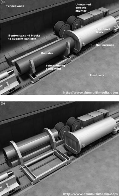
In repository operations, wastes are received and encapsulated in containers at the surface facility. Once sealed, these are considered as waste packages. The waste packages and buffer material are then transported through the access tunnels to the underground facility and then to the disposal panels and emplaced. In addition to experience gained in existing repositories, concepts for a remote-controlled transfer/ emplacement system of waste packages have been established to illustrate a series of operational procedures leading up to the emplacement of the waste packages and buffer materials (Figure 5.8).
To close the repository, access tunnels and boreholes should be appropriately backfilled to isolate underground facilities from the ground surface. In parallel with this, surface facilities should be decommissioned. Large amounts of debris will be produced from the excavation of tunnels and this could be used as backfill material because it is derived from the host rock and it can be procured easily and economically. Backfill materials with low hydraulic conductivity and swelling properties could be obtained from a mixture of such debris and bentonite (cf. GMT in Box 8.1). The backfilling methods for horizontal tunnels and inclines are identified. These methods include block laying, spreading/compacting of the backfill material, spraying and transverse compacting. For the shaft-type access tunnels, a backfilling method that applies compaction gradually from bottom of the shaft would be effective.
4 In some national programmes, this is a regulatory requirement.
136 |
H. Umeki |
Fig. 5.8. (Continued)