

202 |
A. Hooper |
8.3.1. Engineered barriers
8.3.1.1. Corrosion
Waste forms are usually packaged in metal containers that are designed to provide absolute physical containment during the period that the wastes are most radioactive. In vented containers, absolute containment will persist only as long as the repository remains unsaturated and, even then, will apply only to non-gaseous radionuclides. Two approaches may be discerned to materials selection for waste containers. The first is a ‘‘corrosion allowance’’ approach in which a reasonably high corrosion rate is accepted and the container is designed with sufficient thickness to provide the required container longevity. This approach is often used for containers made from plain carbon steel or cast iron. Designers set a target lifetime (e.g., 1000 years) and then calculate the expected metal loss over this lifetime, allowing for the different corrosion rates under aerobic conditions, when localised corrosion, or pitting, is a consideration, and anaerobic conditions (e.g., JNC, 2000). After adding a safety margin, the required container thickness can be obtained. A typical corrosion allowance for cast iron or steel is about 40 mm. Because of their resistance to localised corrosion, cast iron and carbon steel may be considered suitable for a wide range of disposal environments, including salt.
The second approach is one in which the container material is selected to provide a very low corrosion rate. In this case, factors other than corrosion determine the thickness of the container. Materials that fall into this class are stainless steel, Alloy 22 (nickel- chrome-molybdenum), titanium and pure copper. The last of these, pure copper, does not generally react under anaerobic conditions and the extent of corrosion depends principally on the amount of oxygen trapped in the bentonite buffer when it is emplaced and, in addition, reactions with any SO24 contained in the buffer and groundwater. Depending on the groundwater chemistry, this can produce very low corrosion rates, e.g., as low as 50 mm in one million years (King et al., 2001). However, reasonable levels of SO24 in groundwater (e.g., in near-coastal sites) can rapidly make the use of copper canisters untenable (see discussion in McKinley, 1985).The other three materials – stainless steel, titanium and Alloy 22 – all form oxides that passivate the metal so that further oxidation occurs extremely slowly (e.g., Kursten et al., 2004). Of the various types of stainless steel, the 316 grade is usually preferred because of its higher resistance to localised corrosion and stress corrosion cracking. Titanium and Alloy 22 have good resistance to localised corrosion, which includes pitting, crevice corrosion and microbially induced corrosion.
There is a high level of confidence that the general corrosion rates of stainless and carbon steels are sufficiently well-defined over a range of temperatures and chemical conditions to enable the necessary design decisions to be made. The main area where further R&D is required is on localised corrosion under chemical conditions related to specific disposal concepts and host geological formations. In particular, microbially induced corrosion has been raised as an area where more in-depth R&D is required; atmospheric stress corrosion cracking of stainless steels also requires more attention (Kursten et al., 2004). The latter relates to the increasing international trend towards repository concepts that envisage extended periods of reversibility, where waste containers would effectively be in contact with air prior to the emplacement of buffer or backfill materials and subsequent repository sealing and closure.
Research and development infrastructure |
203 |
For the corrosion-resistant metals, the main area where further R&D is required concerns the effect of fabrication on localised corrosion. In the case of the nickelbased Alloy 22 proposed for waste containers at the USDOE’s Yucca Mountain site (see Chapter 3), its corrosion behaviour in the presence of high-salt concentrations and high temperatures is the subject of ongoing R&D to define the envelope of conditions where premature failure can be avoided (e.g., Inhofe, 2006).
The outputs of R&D in this area are used in a variety of ways in repository safety assessments. Typically, the results are used in defining the source term of release of radionuclides from the container, where parameters such as the number of container failures as a function of time, the nature of the failure (e.g., the dimensions of a corrosion-induced hole) and the time for which the absence of failures can be relied upon may be required. Such considerations can provide important feedback to the repository concept. For example, in Belgium, it was determined that an improved concept would be explored which would afford a high-level of confidence in the integrity of the container for HLW/SF such that radionuclides could not be released to the clay host formation during the period of high thermal output from the waste. The concept called for R&D on the corrosion of the carbon steel to be used for the container under alkaline conditions prevailing in the cement-based system currently under consideration in Belgium.
8.3.1.2. Buffer and backfill materials
Notwithstanding the above design example, it was noted in Chapter 5 that, for most HLW/SF repository designs, compacted bentonite is the most usual choice of buffer/ backfill. R&D has established the key properties of this material: swelling on contact with water, plasticity, low subsequent permeability when hydrated (Pusch, 2001, 2002) and its ability to sorb radionuclides (e.g., Bradbury and Baeyens, 2003). Through projects such as FEBEX and Prototype Repository (see below for details), R&D is ongoing to establish the coupled effects of heat, geochemistry and hydraulics on the resaturation rate of compacted bentonite at full (or near full) scale and with geometries that are as complex as the real repository situation.
While the WIPP repository uses a magnesium oxide buffer, other disposal concepts in salt propose the use of crushed, previously excavated salt as a buffer. A recent summary is provided in Stu¨hrenberg and Heusermann (2004).
As noted above (and in Chapter 5), cement grouts are the main candidate buffer material for most L/ILW. The Nirex Reference Vault Backfill (Nirex, 1997b) is typical: it is designed to condition inflowing groundwater to pH values greater than 10 for periods of 100,000 years or more. It has a relatively high porosity and permeability to provide ample surfaces for sorption and the ability to disperse gas produced by the waste. To develop the backfill material and confirm its compliance with all safety-related specifications, extensive use was made of conventional cement and concrete laboratory testing methods.
Once the waste has been emplaced and surrounded with the appropriate buffer material, the next step is to backfill and then seal the access ways. For concepts that use a bentonite buffer, the backfill needs to offer mechanical resistance to the buffer so that the swelling pressure that develops within the buffer is sufficient to cause the saturated bentonite to flow into any voids and thus produce the required low permeability. More generally, the aim is to produce a combined backfill-and-seals system
204 |
A. Hooper |
|
Plug |
|
Water/Gas |
Granite |
migration |
Access drift
Gas injection
Gas migration
(Water saturated)
Backfill |
m |
|
3.0 |
||
|
|
Concrete silo |
|
Gas |
m |
|
4.5 |
||
|
||
|
Construction |
|
|
joint |
|
Bentonite-sand |
|
|
mixture |
|
ø 4.0 m
High permeability shear zone
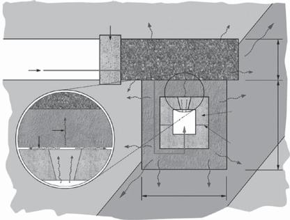
Fig. 8.5. Experimental concept for the GMT. The gas evolved from the silo moved through the concrete and into the bentonite/sand buffer and, eventually, into the host rock and access tunnels (image courtesy of Nagra and RWMC).
whose long-term permeability is as low as that of the adjacent rock. The permeabilities required of the backfill can be achieved relatively simply using compacted, graded, excavated rock spoil mixed with bentonite or OPC (Pusch, 2001, 2002) and the plugs can be made using OPC, low pH cements, natural stone, bentonite or bentonite/sand (see, e.g., Figs 8.5 and 8.6 in Nagra, 2002b). A more difficult task is to ensure that the required permeability of the backfill/seal system is maintained throughout the post-closure period. The most onerous period will occur during repository resaturation, when the hydraulic heads across the seals and backfill may be at their greatest.
8.3.1.3. Container fabrication
As noted in Chapter 5, radwaste containers are designed to have high endurance; careful material selection, rigorous testing and the application of detailed quality standards in fabrication provide assurance that the required quality will be achieved. In the case of stainless steel containers for ILW, the containers are usually constructed in an all-welded design with a bolted-on lid: 316 stainless steel is fairly easily welded and standard welding practice can be used.
For the containers used for HLW/SF, however, significant R&D may still be required to design a suitable fabrication technique. To do this for its copper canister, e.g., SKB opened its Canister Laboratory in 1998. Here, SKB has investigated methods of manufacturing the canister and the steel inserts – a major task when it is recalled that the total package is nearly 5 m tall and more than 1 m in diameter and weighs between 25 and 27 tonnes when filled with fuel. A particular challenge was how to accomplish the final