

Repository design |
117 |
needs to be an ongoing process and it is therefore necessary to keep the prioritisation under review.
It should be noted that requirements management theory is of general relevance to product design and that the theory needs to be tailored to the particular product in question. Different waste disposal programmes might be expected, therefore, to apply the theory in slightly different ways to suit their particular context. There is, as yet, only limited experience in the practical application of requirements management to waste disposal programmes.
5.3. Concept development
The multi-barrier principle generally provides the foundation for the design strategy, but flexibility exists for weighting on the different safety functions provided by a disposal system. There is diversity in repository concepts and EBS designs (EC-NEA, 2003; NUMO, 2004), but agreement exists on the definition of the EBS and on its primary role: the containment and long-term minimisation/retardation of radionuclide releases. All radioactive waste management programmes include an EBS providing multiple barriers to radionuclide migration, and reserves of performance greater than required for compliance with safety criteria (e.g., dose or risk limits). Although the EBS plays a significant role in providing the required level of disposal system performance, there are few specific regulatory requirements on the EBS that go beyond that for a robust system of multiple barriers.
5.3.1. Major components of the disposal system and safety functions
The geological disposal systems under investigation in many national programmes involve the excavation of a repository at a depth of several hundred metres in an appropriate host rock in a suitable geological environment (see Chapter 4).
In the most common approach, vertical shafts or an access tunnel, or a combination of these, are then excavated to the planned depth. At this depth, horizontal disposal galleries are excavated, where the waste packages are emplaced and surrounded by the selected buffer material. Even after backfilling and sealing of the repository, the waste still remains technically retrievable for long periods of time, basically depending on the duration of the waste package integrity.
The major natural and engineered components of a geological disposal system can be thought of in the following groups:
the EBS and repository
&waste form
&container (or overpack)
&buffer/backfill material
&tunnel supports
&sealing systems (plugs, grout, etc.)
the excavation disturbed zone (EDZ): the rock immediately adjacent to the excavations
the geosphere
the biosphere
118 |
H. Umeki |
With the exception of the US programme, there is generally good consistency amongst national EBS designs for spent fuel (SF) and high-level vitrified waste (HLW) disposal, but less so for low and intermediate level waste (L/ILW) (EC-NEA, 2003):
For SF, the main components are UO2, mixed uranium and plutonium oxides (MOX) and other waste matrices, steel or copper-iron containers, copper, steel or Ni-alloy overpacks and bentonite or bentonite-based (e.g., sand-bentonite mixtures) buffers.
For HLW, the main components of the EBS are a borosilicate glass matrix, steel containers/overpacks and bentonite or bentonite-based buffers.
For L/ILW, the main components of the EBS include a wide variety of waste matrices, e.g., concrete-conditioned wastes, steel or concrete containers and a wide variety of backfill materials, including concrete, bentonite-based materials, salt-concrete and magnesium oxide.
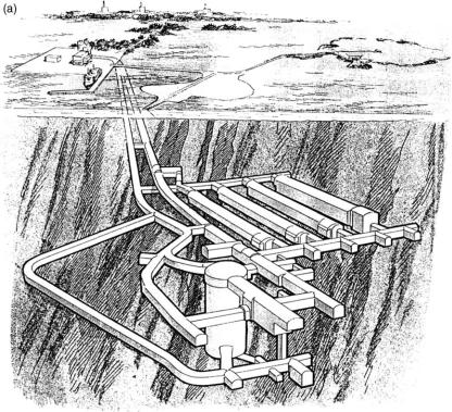
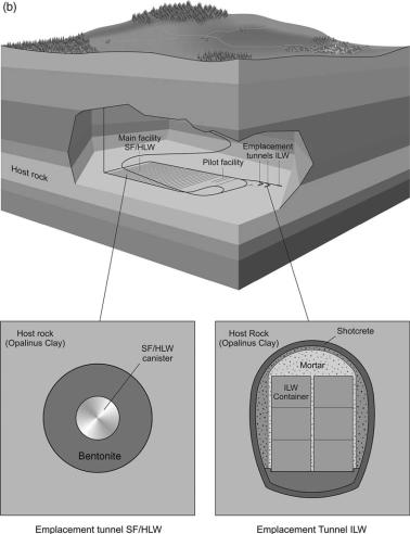
The greater variation in the L/ILW disposal concepts reflects the greater number of L/ILW waste streams and the wide range of different disposal sites. Figure 5.2 shows examples of repository layouts for L/ILW and co-disposal of SF, HLW and long-lived ILW, taking the features of the disposed waste into account.
The geological disposal system should contain the short-lived, highly active radionuclide content of the waste completely, i.e., until radioactivity has decayed to insignificant levels. There is broad agreement, however, that the majority of repository
Fig. 5.2. (Continued)
Repository design |
119 |
Fig. 5.2. (a) Example of a cementitious L/ILW repository layout (artist’s impression of the Swedish L/ILW repository at Forsmark) (image courtesy of SKB). (b) Example of a co-disposal repository layout (Nagra, 2002) (image courtesy of Nagra).
concepts cannot be relied on to completely contain all the long-lived radionuclides present in the wastes (IAEA, 1995; ICRP, 2000). Consequently, after closure, a geological disposal system can be seen to have different functions at different times in the future. Such functions are summarised as:
Isolation from near-surface processes and from human activities;
Protection of the biosphere: shielding from the radioactivity of the wastes at its peak in the first few hundred years after disposal;
Early containment: substantially complete containment of short-lived radionuclides for several hundreds or thousands of years;
Delaying and limiting the rate and the consequent concentration in which radionuclides will be released from the progressively degrading EBS into the geological environment
120 |
H. Umeki |
and eventually transported to the biosphere: this is achieved by a combination of physical and chemical mechanisms which ensure limited groundwater flux to the waste and from the repository to the biosphere, high chemical durability of the waste form, radionuclide solubility limits, filtration of colloids, organic matter and microbes, sorption or precipitation of radionuclides onto surfaces in the EBS and rocks, etc.;
Dispersion and dilution.
These functions are achieved by selecting suitable geological environments for disposal and then adjusting the repository designs and the EBS concepts to the environments. Most concepts are based on a multi-barrier system which includes a massive, geochemically robust EBS that could provide large safety margins at a range of different potential sites.
In the case of HLW/SF, the key components of the EBS are a massive metal overpack and a thick buffer of compacted bentonite/sand. These barriers were chosen to provide high performance, with a highly conservative design using well-known materials. Figure 3.5 illustrates the main features of this EBS and indicates the multiple processes which work together to provide a robust isolation system.
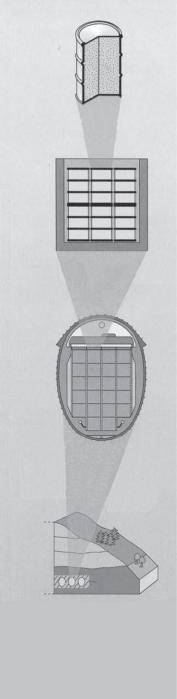
The L/ILW including metal, organics and inorganic materials is typically mixed with either cementitious materials or bitumen and placed in a steel drum. The waste drums are then packaged in a steel or concrete container, which is emplaced in a cavern excavated deep underground. The cavern is typically backfilled with cement-based material. Figure 5.3 gives an example of a cementitious L/ILW EBS design and its expected functions. Hulls and ends from reprocessing of spent nuclear fuel are heat generating and may also be classified as ILW to be directly encapsulated in metal canisters.
The main functions of the EBS components can be summarised as follows:
The waste matrix is designed to provide a stable waste form that is resistant to leaching and gives slow rates of radionuclide release for the long-term (decades for LLW, up to several hundred thousand years for HLW/SF).
The container/overpack is designed to facilitate waste handling, emplacement and retrievability, and to provide containment for hundreds to thousands of years or longer, in particular for HLW/SF.
The buffer/backfill is designed to stabilise the repository excavations and the thermo- hydro-mechanical-chemical (THMC) conditions, and to provide low permeabilities and diffusivities and long-term retardation of radionuclides.
The other EBS components are designed to prevent releases via tunnels and shafts and to prevent access to the repository.
5.3.2. A structured approach for concept development
Based on the identified constraints on repository design and layout, possible repository concept(s) for the potential host rock(s) in a given siting environment can be selected from possible options described in the previous section. In principle, the selection should include only designs which appear safe and practical based on existing technology (or reasonably expected developments thereof). Such site-specific repository concepts are then analysed by a simple SA with input from the site geosynthesis. It may be necessary to iterate such an assessment several times (e.g., Nagra, 1985, 1994, 2002), with increasingly detailed specification of the repository concept and its interaction with
Repository design |
121 |
Solidification matrix:
Low radionuclide release rate
Container, container infill, waste drums:
Low solute transport rates
Radionuclide sorption
Chemical buffer
Emplacement cavern, lining and backfill:
Limited water access
Delay start of release
Low solute transport rates
Chemical buffer
Radionuclide sorption
Allow gas escape
Geosphere
Repository zone
Geological barriers repository zone:
Low water flux Favourable hydrochemistry Mechanical stability
Geological barriers geosphere:
Retardation of radionuclides (sorption, matrix diffusion)
Reduction of radionuclide concentrations (dilution, radioactive decay)
Physical protection of the engineered barriers (e.g., from glacial erosion)
Fig. 5.3. Example of a cementitious L/ILW EBS design (Nagra, 1999) (image courtesy of Nagra).
122 |
H. Umeki |
the host rock. The output of such an analysis will be repository concepts which can be reasonably expected to meet regulatory guidelines for long-term safety.
A range of widely differing factors needs to be considered when selecting between alternative design options, or when refining selected designs, such as operational and post-closure safety, cost, practicability, feasibility, stakeholder and societal opinions and programmatic risk. Uncertainties will exist in all of the factors that need to be considered. An important part of justifying any particular design (or justifying the selection of a particular disposal site) is a demonstration that potentially suitable alternatives have been considered and that the selected option represents, in some sense, ‘‘the optimum choice’’ or ‘‘best solution’’, taking into account a range of relevant factors. In Japan, for example, these factors (termed ‘‘design factors’’) for systematically and comprehensively assessing design alternatives have been identified as (NUMO, 2004):
Long-term safety
Operational safety
Engineering feasibility / QA
Engineering reliability
Site characterisation / monitoring requirements
Retrievability
Environmental impact
Socio-economic aspects
Taking these factors into account, a structured approach for iterative development of repository concepts along with a site characterisation procedure has been developed, which not only allows the repository design to be tailored to the site but also feeds back to allow optimisation of the characterisation programme. This approach will also include development of top-level tools for information collation and synthesis, which will feed back to allow prioritisation and optimisation of the associated national R&D programme. The work involved will be fully documented, not only to provide a mechanism for quality assurance via expert review but also to inform key stakeholders of progress – with special emphasis on the local populations of the areas investigated.
Ideally, the output of such repository concept studies will be the definition of a range of potential designs/layouts for a number of different sites. Sensitivity analysis associated with safety assessments will identify the key site parameters which determine the practicality and long-term safety of each. If the number of sites/designs is impractically large, some form of multi-attribute (or multi-criteria) decision analysis (MAA) may be used to rank options – including consideration of additional factors such as cost and acceptability (e.g., ease of monitoring, reversibility) (e.g., Bel et al., 2004).
The MAA method allows a traceable evaluation of options against a set of agreed criteria. Using such structured methods, it is also possible to include stakeholders with a wide range of skills and experience in identifying and comparing options. The set of criteria should be comprehensive and, to the extent possible, each criterion should be discriminatory, unambiguous and independent. In the analysis, each option is scored against the criteria and the sum of the scores then indicates the preferred option. The analysis may be enhanced by attaching weightings to the scores that account for stakeholders’ values on the relative importance of the criteria. The criteria for evaluating design options include those relevant to factors mentioned above, e.g., long-term safety, operational safety, etc. More detailed criteria may also be considered according to