

148 |
P.A. Smith |
work may be undertaken, e.g., to acquire new data or develop new models and computer codes (see also comments in Chapter 8 on the R&D programme).
The SA is then carried out. It is often the case that requirements for improvements to the assessment basis are identified in the course of the SA, e.g., to fill gaps or to resolve inconsistencies in the available data. Even if not specifically requested by the safety assessors, ongoing laboratory programmes and site measurements will often generate new and relevant data as the SA is being carried out. At some stage, however, to ensure the traceability of the data used in the assessment, all databases must be ‘‘frozen’’. No newly generated data are then admitted to the databases used by the assessors, although they are, of course, recorded and may be used in future assessments (c.f. comments in Pate et al., 1994). The findings of the SA are then reviewed internally by the safety assessors, to check that the aims of the assessment have been fulfilled and, in particular, that the findings are adequate as a support to decision-making. If not, then either the assessment basis may need to be updated or the assessment itself may need to be extended in its scope, perhaps to explore possibilities or uncertainties that had been overlooked the first time.
Some decisions are the sole responsibility of the repository implementer. Others may require the consent of local or national governments, taking into account reviews by regulators or licensing authorities, or require the direct consent of the local or national population via a referendum (see examples in Chapters 4 and 9). To support external decision-making, the implementer must first satisfy itself that a positive decision to progress to the next development stage is justified in terms of long-term safety by conducting a SA. The implementer must then present the reasons why such a decision is justified to the regulators (and often other external decision-makers) in the form of a ‘‘safety case’’. The safety case, which is discussed in more detail in section 6.5, provides a synthesis of relevant evidence, analyses and arguments, including those from SA. It may also give guidance, based in part on the results of the SA, on the R&D, site characterisation and design work that should be carried out in the course of future stages to address remaining uncertainties and open questions.
6.3. SA tasks
Although there are differences between national programmes in the detailed procedures that are followed, the broad tasks that are carried in the course of any post-closure SA are essentially the same, namely:
carefully describe the initial appearance or state of the repository (i.e., the state of the repository when it has just been closed, taking into account perturbations caused by construction, operation and any pre-closure open period), and consider what changes the repository could undergo in time as a consequence of both internal processes within the repository and external forces,
identify broad scenarios that illustrate the range of possibilities for the evolution of the repository under consideration and its surrounding environment, and
analyse these scenarios, taking into account all relevant uncertainties, to evaluate their consequences for safety.
These broad tasks are described in the following sections.
Safety and performance assessment of repository |
149 |
6.3.1. System description
Detailed scientific understanding of FEPs that define the initial state of a repository and its environment, and determine how this will change over the course of time, provides the foundation of all post-closure SAs. According to the NEA (2004a), the system components that are described should include the host rock and surrounding geological environment, the surface site, waste inventory, the engineered barriers and particular features of the repository layout or design with implications for post-closure safety, e.g., the arrangement of seals in the backfilled tunnels (see Chapter 5). The description of each generally includes:
its geometry and constituents,
its safety functions (as discussed further below), and
a general description of its expected evolution and performance, including all relevant uncertainties.
Relevant uncertainties are, where possible, quantified or bounded, taking into account how uncertainties vary over time. Expected FEPs that are potentially important for system safety, as well as those that are considered unlikely but still plausible, may be included, as are design constraints or criteria, such as the maximum temperature that is expected to occur within the buffer.
The system description generally includes a description of (or references to) site characterisation procedures and field, laboratory, natural analogue and URL studies that have been carried out in support of the SA. Furthermore, it is clearly important that the system considered in the SA is one that can be implemented (i.e., constructed, operated and closed) in practice using currently available technology. An evaluation of engineering feasibility does not generally form part of the SA and is usually considered in a separate study (see Chapter 5). The SA may, however, refer to the findings of such a study and may also include a description of any QA procedures (Chapter 5) and waste acceptance criteria (Chapter 2) that ensure that the specifications of the engineered features, including the waste form itself, will be met.
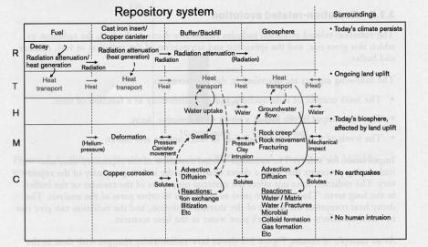
In the Swedish SR 97 SA (SKB, 1999), processes affecting the evolution of the repository and its environment, and their various interconnections, are illustrated schematically (Fig. 6.3) in THMC diagrams, where the processes are categorised as thermal (T), hydraulic (H), mechanical (M) and chemical (C). Some processes are also radiation-related (R). The diagrams show the relationship between the variables, such as temperature and groundwater composition, that define the system at any time and the processes that affect its evolution.
In the Swiss SA for Project Opalinus Clay (Nagra, 2002a–d), the system description comprises separate descriptions of the ‘‘system concept’’ and the ‘‘safety concept’’. The description of the system concept identifies the key features of the system, events, processes and interactions that may affect its evolution and the possible paths that its evolution might take. On the basis of the system concept, a description can be made of how the system provides safety; this is the safety concept. Typically, a repository and its environment provide safety via a number of safety functions, such as:
isolation and limited accessibility of the waste from the human environment,
long-term confinement and decay of radionuclides within the multi-barrier EBS (e.g., due to the integrity of waste canisters or containers and the stability of the waste forms), and
150 |
P.A. Smith |
Fig. 6.3. The main features and processes of the repository system in the base scenario of the SR 97 SA (from Fig. 3.2 of SKB, 1999).
attenuation of releases to the environment (e.g., due to dispersion and slow transport coupled with radioactive decay in the host rock),
The safety concept is essentially a description of how the chosen site and design are expected to provide these safety functions and limit the consequences of any potentially detrimental phenomena and uncertainties.
When describing the safety functions, their changing role or reliability in different periods or time frames has to be considered. Figure 6.4 shows an example of this from the Belgian SAFIR-2 study (ONDRAF, 2001a,b). In this example, a ‘‘latent function’’ is one that only operates if other safety functions (unexpectedly) fail to operate. A ‘‘reserve function’’ is one that may well enhance the level of safety, but where uncertainties are such that it cannot currently be relied upon with confidence within a given time frame.
6.3.2. Identification of scenarios and cases for analysis
The system description, or more specifically the safety concept, explains how a system has been sited and designed to provide safety. It is, however, also necessary to evaluate whether the level of safety provided is sufficient to satisfy relevant safety criteria, taking into account all potentially relevant detrimental phenomena and uncertainties.
In some cases, it may be adequate to treat uncertainties using conservative model assumptions and pessimistic parameter values and estimates of likelihood, which ensure that the evaluated radiological consequences of a repository error on the side of caution. There are, however, limitations to this approach, particularly at the early stages of a project. In particular,

|
|
|
|
Safety and performance assessment of repository |
151 |
|||||||||||||||
|
|
|
|
|
|
|
|
|
|
|
|
|
|
|
|
|
|
|
|
|
|
|
|
|
|
|
|
|
|
|
|
|
|
|
|
|
|
|
|
|
|
|
1000 |
[year] |
1022 |
1033 |
1044 |
|
|
1066 |
|
|
|
|
|
|
|
|||||
|
|
|
|
|
|
|
|
|
|
|
|
|
|
|
|
|
|
|
|
|
|
|
operationalphase |
thermalphase |
|
isolationph.. |
geologicalphase |
|
|
|
|
|
|
|
|
|
|||||
|
|
|
|
|
|
|
|
|
|
|
|
|
|
|
|
|
|
|
||
|
|
|
physical confinement (C1 + C2) |
|
|
reserve |
|
|
|
|
|
|
|
|
|
|
|
|
||
|
|
|
|
|
|
|
|
|
|
|
|
|
|
|
|
|
|
|
|
|
|
|
|
|
|
|
|
resistence to |
|
reserve |
|
|
|
|
|
|
|
|
|
|
|
|
|
|
latent function |
|
leaching (R1) |
|
|
|
|
|
|
|
|
|
|
|
||||
|
|
|
|
|
|
diffusion and |
retention (R2) |
|
|
|
|
|
|
|
|
|
||||
|
|
|
|
|
|
|
|
|
|
|
|
|
|
|
|
|
|
|||
|
|
|
|
latent function |
|
|
|
|
dilution and dispersion (D) |
|
|
|
||||||||
|
|
|
|
|
|
|
|
|
|
|
|
|
|
|
|
|
|
|
||
|
|
|
|
|
limited accessibility (L) |
|
|
|
|
|
|
|
|
|
|
|
||||
|
|
|
|
|
|
|
|
|
|
|
|
|
|
|
|
|
|
|
|
|
|
|
|
|
|
|
|
|
|
|
|
|
|
|
|
|
|
|
|
|
|
Key to symbols
Physical confinement (C): isolation of the radionuclides from their immediate environment, especially from water, achieved by:
•water tightness (C1): primarily associated with the engineered barriers, and
•limitation of water influx (C2): mainly associated with the natural barrier but also the capacity for certain engineered barriers to delay the ingress of water.
Delay and spread the release (R): after, or in the event of, breaching the physical containment, this second function delays and spreads the migration of the radionuclides towards the biosphere for, and over, as long a time as possible, achieved by:
•difficulty of leaching (R1): the system inhibits the release of the radionuclides from the matrix in which they are contained (spreading the release over time), and
•diffusion and retention (R2): the system retains the radionuclides once released from their matrices (locally in the EBS and also in the near geosphere).
Dilution and dispersion (D): in the long term, this function (associated with the further geosphere and biosphere interface) ensures that the radionuclides will be diluted and dispersed by flows of groundwater in the geosphere and surface water in the biosphere.
Fig. 6.4. The safety functions identified in the SAFIR-2 study and the time frames over which they are expected to operate (from Fig. 2.6 of ONDRAF, 2001a).
it is not always possible to decide in advance of SA calculations being carried out which alternative scenarios, model assumptions or even parameter values are the more conservative or pessimistic, and
if an extreme combination of multiple conservative or pessimistic assumptions is made to pre-empt any objection that some unfavourable situation has been excluded, then unrealistic or highly improbable combinations may be selected and it may not be possible to satisfy relevant regulatory criteria. This can then impact public confidence at a later time in the programme (see also Chapter 9).
In the early stages of a project, when information is limited and uncertainties may be large, the usual aim of SA is not to demonstrate that relevant safety criteria are satisfied for a fixed site and design. Rather, it is to show that there are reasonable
152 |
P.A. Smith |
prospects for satisfying these criteria following further R&D, siting studies, site characterisation work and design optimisation to reduce, avoid or mitigate the effects of the most important uncertainties. A purely conservative or pessimistic approach does not give a basis for deciding which uncertainties are the most important in terms of repository performance.
Thus, the impact of at least the more well-defined uncertainties is usually investigated by considering a wide range of possibilities for system evolution and evaluating their consequences using mathematical models or more qualitative reasoning (although a conservative/pessimistic approach may still be used for some uncertainties, as discussed further below). Calculations are generally carried out using computer codes to solve the governing equations of mathematical models, with given sets of parameter values. They may be performed
deterministically (i.e., with the models and parameter values defining each calculation individually specified by the safety assessor to investigate the impact of particular uncertainties),
probabilistically (i.e., with parameter values sampled from probability distribution functions), or
using some combination of these methods.
The impact of different uncertainties on the evolution of the system can vary widely, as can the methods used to evaluate their impact. The impact of some uncertainties can be evaluated by simply adjusting the value of a parameter describing, say, the spatial extent of a feature, the rate of a process, or the timing of an event. Other uncertainties are such that alternative models may have to be considered for individual processes, or groups of processes. Finally, there may be uncertainties that fundamentally affect the path that the evolution of the system may take and the ways in which the exposure to radionuclides could conceivably take place at some future time. For this reason, some SAs have adopted a categorisation of uncertainties, such as that shown below from the Swiss Project Opalinus Clay SA (Nagra, 2002a), which differentiates between scenario uncertainties, which are most far-reaching in their impact on system evolution, conceptual or model uncertainties and parameter uncertainties (see Box 6.1).
A number of different models and scenarios can be built into a single computer code and switched on or off via an input parameter. In this sense, all uncertainties can be described as parameter uncertainties. Nevertheless, the categorisation of uncertainties in the manner indicated above can provide a useful way of organising the potentially very large number of calculations that must typically be performed in a SA according to the types of uncertainty that they address.
Often, a ‘‘base’’ or ‘‘reference’’ scenario is analysed first and in most detail. A number of other scenarios are then analysed in which the course of events differs from that of the base or reference scenario as a result of specific scenario uncertainties. Figure 6.5 shows the classification of scenarios in the Japanese H12 SA (JNC, 2000a–d).
In many SAs, in the base or reference scenarios the repository is postulated as being built according to design specifications and present-day conditions and the surroundings, including the climate, are assumed to persist for all times considered. Figure 6.3 shows the main features and processes of the repository system in the base scenario of the Swedish SR 97 SA (SKB, 1999), and the assumptions regarding its surroundings, such as the persistence of present-day climate.
Safety and performance assessment of repository |
153 |
Box 6.1. Example of a system for categorising uncertainties for treatment in SA (from Section 3.4 of Nagra, 2002a).
Scenario uncertainty is the uncertainty in the broad evolution of the repository and its environment. This can also be considered as the uncertainty related to inclusion, exclusion or alternative realisations of FEPs that may affect this broad evolution.
Conceptual uncertainty is uncertainty in the assumptions or conceptual model used to represent a given scenario or set of FEPs, including uncertainty related to the existence of plausible alternative conceptual models.
Parameter uncertainty is the uncertainty in parameter values used in a model. Parameter uncertainty can be due to spatial variability and evolution over time of relevant properties and to uncertainty in the extrapolation of observations from laboratory or natural system conditions and scales of space and time to the conditions and scales relevant to the repository and its environment. Parameter uncertainty can also arise from uncertainty in the models used to interpret the raw data used to derive the parameters required for SA models.
Scenarios considered in the H12 SA
|
|
|
|
|
|
|
|
|
|
|
|
|
|
|
|
|
|
|
|
|
|
|
|
|
|
|
|
“Groundwater Scenarios” |
|
|
|
“Isolation Failure |
||||||
|
Radionuclides are transported to the |
|
|
|
Scenarios” |
|||||||
|
biosphere by flowing groundwater |
|
|
The human environment is |
||||||||
|
|
|
|
|
|
|
|
|
|
|||
|
|
|
|
|
|
|
|
|
|
affected due to the physical |
||
|
|
|
|
|
|
|
|
|
|
isolation of the waste being |
||
|
Base Scenario |
|
Perturbation |
|
|
compromised by: |
||||||
|
- The geological environment |
|
Scenarios |
|
|
- |
Uplift and erosion |
|||||
|
|
|
|
|
|
|
- |
Direct magma intrusion |
||||
|
remains stable and the |
|
Account is taken of: |
|
|
|||||||
|
|
|
|
- |
Direct human intrusion |
|||||||
|
present day geological |
|
- Natural phenomena |
|
|
|||||||
|
|
|
|
- |
Meteorite impact, etc. |
|||||||
|
conditions remain unchanged |
|
- Future human activities |
|
|
|||||||
|
|
|
|
|
|
|
||||||
|
indefinitely into the future. |
|
- Initial EBS defects etc. |
|
|
|
|
|
||||
|
|
|
|
|
|
|
|
|
|
|
|
|
|
|
|
|
|
|
|
|
|
|
|
|
|
Fig. 6.5. Scenarios considered in the Japanese H12 SA (adapted from JNC, 2000a).
Within each scenario, conceptual uncertainties may give rise to various possibilities for how individual processes or groups of processes are modelled and parameter uncertainties may give rise to a range of possibilities for the parameter values to be assigned to these models. Thus, e.g., in the methodology used in the Swiss SA for Project Opalinus Clay, a scenario is represented by a group of individually analysed ‘‘assessment cases’’. Within each scenario group, sub-groups address alternative possibilities arising from conceptual uncertainties. Finally, individual cases within each subgroup address alternative possibilities arising from parameter uncertainties. This hierarchy of assessment case groupings is illustrated in Fig. 6.6.
Some SAs also examine ‘‘what-if?’’ cases that, while not necessarily physically impossible, lie outside the range of possibilities reasonably expected to occur according

154 |
|
P.A. Smith |
|
Different scenarios to |
Different conceptualisations |
Different parameter sets to |
|
illustrate scenario uncertainty |
of a scenario, illustrating |
illustrate parameter uncertainty |
|
|
|
conceptual uncertainty |
for one conceptualisation |
Alternative |
Reference |
Reference conceptualisation |
Reference parameter set |
scenario |
scenario |
|
|
|
|
|
Alternative parameter set |
|
|
Alternative conceptualisation |
Alternative parameter set |
|
|
|
Alternative parameter set |
Alternative |
Alternative |
Alternative conceptualisation |
|
scenario |
scenario |
|
|
Alternative conceptualisation
Fig. 6.6. Schematic illustration of a hierarchy of assessment case groupings. Groups of assessment cases illustrate each scenario. Within these groups, sub-groups illustrate alternative conceptualisations. Within these sub-groups, individual cases illustrate alternative parameter sets (from Fig. 3.7.3 of Nagra, 2002a).
to the scientific understanding available to the safety assessors. Although whether or not particular scenarios, model assumptions and parameter values are in fact impossible is often partly a matter of subjective judgement, if the system can be shown to provide safety even in extreme ‘‘what-if?’’ cases, then this can, to some extent, preempt any criticism that the chosen ranges of possibilities are too narrow and guard against the possibility that some significant FEPs or sources of uncertainty have been overlooked.
Finally, it must be mentioned that, in SA, the treatment of uncertainties associated with the biosphere and with future human actions is generally different to the treatment of uncertainties associated with the near-field and geosphere. This is in part because some aspects of the evolution of the biosphere, and also the nature and timing of future human actions, become highly speculative even over relatively short times into the future. They are affected by uncertainties that are difficult to quantify or bound (e.g., what will humans be eating in 1000 years2) and so reliable, detailed modelling is not possible, although these uncertainties can have a significant effect on evaluated levels of safety.
The role and treatment of the biosphere in long-term SA has been discussed extensively in international fora. The consensus that has developed suggests that a reasonable approach is to separate the assessment of the biosphere from that of the repository and its geological environment, as proposed, e.g., by an NEA ad hoc working group (NEA, 1999b), and to develop a range of credible illustrations for the biosphere, thereby exploring the uncertainty related to it (IAEA, 1999; Sumerling et al., 2001). For example, in the Swiss Project Opalinus Clay SA (Nagra, 2002a), the majority of the assessment
2 As an example of this, who could have guessed that the consumption of spinach in the USA would increase 20-fold within a few years of the introduction of the cartoon character ‘‘Popeye’’?