

Development of geological disposal concepts |
45 |
In the past, different options for the management of various radioactive wastes have been considered including:
Geological disposal
Shallow land burial
Disposal in space
Disposal in/under the polar icecaps
Disposal on or beneath the seabed (including deep-ocean trench disposal)
Partitioning and nuclear transmutation
Storage until activity levels decay to below regulatory limits followed by ‘‘standard’’ waste disposal
Indefinite storage at or near the surface.
First, the basis for geological disposal is examined in more detail; the differences between this and shallow land burial are outlined and then some examples of ‘‘conventional’’ repository concepts are presented for illustration, followed by a consideration of the alternatives.
3.3. Geological disposal
3.3.1. Definitions and comparison with near-surface disposal
First, the depth of a facility has to be considered to determine if it can be classified as geological disposal or not. Currently, repository types may be categorised into:
1.Shallow/near-surface (up to a few tens of metres deep) for the disposal of LLW (and some L/ILW-SL). These repositories, including Drigg in the UK, Centres de la Manche and de l’Aube in France (Fig. 3.3) and Rokkasho 1 and 2 in Japan, are located at or near the surface (‘‘tumuli’’) due to the predominantly low activity and short half-lives of the waste contained, hence not requiring very long isolation times. An extreme variant is the ‘‘mounded-over reactor’’ disposal option considered in the UK (CoRWM, 2005), which is justified by the reduction in the cost and operational risks associated with reactor decommissioning.
2.Intermediate depth disposal (up to a hundred or so metres below surface) is also under consideration or already implemented in some programmes for shorter-lived L/ILW – e.g., JNFL’s planned L1 repository at Rokkasho, north east Japan, and SKB’s existing SFR repository in southern Sweden (Fig. 5.2a). In these repositories, the safety concepts and site characterisation techniques and approaches are much more akin to deep geological repositories than shallow land burial and, as such, they can certainly be classified as geological disposal. The main differences tend to be that the safety case may focus on a significantly shorter timescale than for a deep repository and the geosphere may play a smaller role in containing the wastes (i.e., a higher weighting may be placed on the performance of the EBS).
3.Deep disposal (several hundred metres to several km) is the generally preferred option for longer-lived and highly active wastes. Such repositories for long-lived ILW are operational (e.g., WIPP in Carlsbad, New Mexico, USA), are in the process of closure (e.g., Morsleben, Germany) or are in the process of being licensed

46 |
I.G. McKinley et al. |
(Konrad, also in Germany). Several deep repositories for HLW/SF are in the planning stage, with those in the USA, Finland and Sweden being particularly advanced.
For the purposes of this chapter, the term ‘‘geological disposal’’ will be restricted to concepts in which the geosphere serves as a key component of safety. This thus excludes most options which fall under category 1 above, although, for options which lie 10 m or more below surface, the extent to which the geosphere acts as a barrier can be highly host rockand site-specific. It is important, however, that the implied correlation of depth with activity (or hazard) of the waste is not interpreted too rigorously. For various reasons, several countries have developed or planned deep geological disposal options for all types of waste – including LLW (e.g., Switzerland).
The choice between shallow land burial and deep(er) disposal varies from country to country. Often, it is based on an evaluation of the risk posed by the particular wastes – but other factors also play a role. Cost is an obvious component, which is related to the quantity of waste, the price of land and associated infrastructure and the affluence of the implementing organisation. Regulatory requirements are also clearly critical, although these do change with time. In general, these have become more stringent in recent years, reflecting growing environmental awareness (and national affluence) and practices which may have been considered acceptable in the past and might not meet current or future requirements. It should also be noted that some facilities may have relaxed requirements – e.g., those associated with military projects; nevertheless the extent to which exceptions are allowed may also change with evolving socio-political boundary conditions. The extent to which changing standards are back-applied to existing facilities is variable – and may again be associated with costs.
Certainly, VLLW and many L/ILW types which contain predominantly short-lived radionuclides can be safely buried in shallow facilities which include suitable engineered barriers. It should be emphasised, however, that these are not ‘‘dumps’’, but repositories engineered to meet higher safety levels (compare Figs 3.2 and 3.4). In principle, such wastes are no more toxic than other wastes managed by this approach and have the distinct advantage that their toxicity decays with time. For higher activity/longer lived waste, the safety of this option is less evident. Unfortunately, shallow burial has had a poor record in the past, as instances of simple dumping of problematic waste (such as the soil-cover trenches for transuranic solids and ‘‘soak-away’’ trenches for highly active liquid wastes mentioned in section 3.2) has led to a legacy of contaminated sites which require extremely costly remediation (or which will be ‘‘indefinitely’’ removed from public access)1.
More sophisticated engineered structures have been developed over the last couple of decades (e.g., Fig. 3.4), but associated safety cases generally also include a period of control of site access, possibly involving monitoring with options for repair, refurbishment or remediation if required. There is extensive debate on the required length of such institutional control and the extent to which it can be assured due to social uncertainties (see also a discussion of this topic for the long-term storage option in section 3.4.4).
1 For further information, see, e.g., http://www.hanford.gov/swift/ and http://ornl.gov/sci/env_rpt/aser2000/ chap3.pdf for information on the US Hanford and Oak Ridge sites, respectively.
Development of geological disposal concepts |
47 |
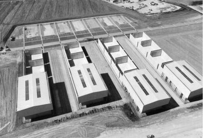
Fig. 3.4. Photograph of the Centre de l’Aube (France) surface repository for LLW. Waste packages will be placed in the large, open concrete compartments (mid-field) and, after they are full, each will be closed with a concrete roof and the entire site then covered with an earth and clay ‘‘cap’’ (Image courtesy of Nagra).
Near-surface disposal is, nevertheless, used extensively for a wide range of L/ILW types in many national programmes, often with specified institutional control periods of hundreds of years. The total number of such facilities given in the literature varies from about 40 (IAEA, 2006) to 100 (WNA, 2001) – this range probably reflecting whether or not military facilities are included and if multiple disposal facilities at a single site are counted separately. The number of further facilities in the planning stage is generally estimated to be about 30 (e.g., IAEA, 2006). Despite the widespread use of this method, the recognition of the vulnerability of near-surface facilities to climate change (and terrorist attacks) has recently resulted in much stringent critical review of such options – even for LLW (see, e.g., McCombie, 1997; Defra, 2006). Certainly, for higher activity wastes, geological disposal appears to be increasingly favoured over near-surface options.
3.3.2. Development of geological disposal concepts
For deep geological disposal, a wide range of concepts has been studied, but effort is usually focused on emplacement in specially constructed underground tunnels or caverns. A pre-requisite is geological stability, but many potential host rocks have been identified, including crystalline basement, salt, basalt, tuff and a range of argillaceous sediments. In all cases, a multiple barrier concept (see example in Fig. 3.5) has been adopted (an overview of concepts worldwide and their evolution with time is provided by Witherspoon, 1991, 1996; Witherspoon and Bodvarsson, 2001, 2006). It is noticeable, however, that the relative weighting in the safety concept of the EBS and the geological barriers (geosphere) varies considerably between national programmes
48 |
I.G. McKinley et al. |
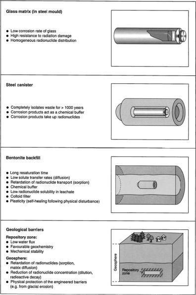
Fig. 3.5. An example of the multi-barrier concept for vitrified HLW developed in Switzerland. The glass is poured into a steel fabrication container which is in turn placed in a thick metal overpack (typically carbon-steel) and emplaced axially in a tunnel which is backfilled with compacted bentonite. The EBS is protected by a stable host rock, which also acts to retard any radionuclides which are released by the EBS. (Illustration courtesy of Nagra).
(Table 3.1 and Chapter 5). Generally, these differences reflect obvious features, such as the availability of a particular host rock, or are a consequence of the national regulatory requirements. Nevertheless, many have evolved with time for less obvious reasons, associated, for example, with the preferences of key staff. For older concepts, those

Development of geological disposal concepts |
49 |
Table 3.1
The weighting of particular contributions to safety for some international HLW/SF disposal concepts (after Alexander & McKinley, 1999)
Key contribution |
Country |
|
|
Geosphere |
|
dry (salt) |
Germany, Holland |
unsaturated |
USA (Yucca Mt) |
low water flow |
Canada, Belgium, Switzerland |
|
(argillaceous host rock), Australia (Pangea) |
EBS |
|
canister longevity (copper) |
Sweden, Finland |
chemistry |
Japan, Switzerland (crystalline host rock) |
|
|
involved may have moved on or retired and so, today, there is frequently no clear documentation trail to justify all aspects of selected designs. Further, specific projects may have originally been initiated based on assumptions which have since been shown to be incorrect; evolution of design to engineer around the problems arising leads to rather unusual final concepts (e.g., Box 3.1).
To elucidate the process involved, it is interesting to examine the evolution of repository design by taking two well documented examples, those of SKB’s SF repository in Sweden and Nagra’s HLW/SF repository in Switzerland. Both these programmes were driven by legal requirements to demonstrate the feasibility of deep geological disposal (associated with continued operation of nuclear power plants) and were developed at a time when such concepts were being actively investigated in relatively few national programmes. Nagra and SKB worked very closely in the 1970s and Nagra’s original concept was strongly influenced by the initial KBS-32 Swedish design (C. McCombie, pers. comm., 1996). Due to its wide distribution and assumed stability, SKB planned that the repository would be sited in the crystalline bedrock of the Scandinavian Shield. This was chosen to be about 500 m deep to minimise the risk of future perturbations (e.g., due to glaciation). A copper canister was selected as the overpack for SF, which would be placed axially in 1.78 m diameter holes drilled vertically into the floor of emplacement tunnels (Fig. 3.6). The canister would be surrounded by compacted bentonite and the overlying tunnel backfilled with bentonite and quartz sand (SKB’s ‘‘in-hole emplacement’’ concept; KBS, 1983). The rather complex emplacement procedure was selected to engineer around potential short-circuits which could be caused by the excavation disturbed zone (EDZ) around the tunnels, which, at that time, was an unknown factor.
This design was adapted by Nagra to suit a different waste form (HLW) and prevailing local conditions, resulting in the concept shown in Figure 3.5 (Nagra, 1985). The geological situation in Switzerland is more complex and tectonically active than in Sweden and stability requirements meant that siting was more tightly constrained into a relatively small geographical area in the north of the country. Both sedimentary and crystalline host rock options were present in this area, although early work focused on
2 This study had been preceded by the KBS-1 and -2 studies and the evolution of the designs, etc. can be found there (KBS, 1977, 1978).
50 |
I.G. McKinley et al. |
Box 3.1. The Yucca Mountain Project
As noted in section 3.2, the US programme was the first to begin seriously assessing radwaste disposal and, since the 1950s, has looked at and evaluated a wide range of repository design options (Inhofe, 2006). It is somewhat surprising, therefore, that, despite huge investment of funds, manpower and technical ability, the US programme has come up with an unusual and controversial solution to deep geological disposal of higher activity wastes. Despite the recommendation of the 1955 Princeton Conference that ‘‘Continuing disposal of certain large volume, low-level waste in the vadose zone, above the water table, is of limited application and probably involves unacceptable long-term risks’’ (Princeton, 1955), building a repository above the water table is exactly what is planned for HLW/SF at Yucca Mountain in Nevada.
The process that led to the selection of Yucca Mountain is outlined in Chapter 7, but some of the anomalous characteristics of this project are worth mentioning as they do not fall within the range of generalities which are usually used to describe deep repositories. An original assumption behind the choice of this site was that, because it lay in a desert where transpiration exceeded rainfall and the repository horizon lay above the water table, it would be ‘‘dry’’ and EBS designs were based on this. Unfortunately, it was later found that rainfall involved episodic storms which result in transient, rapid flows of groundwater. In addition, unsaturated repository zones would still have 100 per cent humidity which, combined with an oxidising environment, produces highly corrosive conditions. The area was also found to be close to sites of recent volcanic activity and surrounded by active faults which give rise to relatively frequent earthquakes. To make matters worse, several key contractors were found to have falsified certain quality assurance documents (Garrish, 2005).
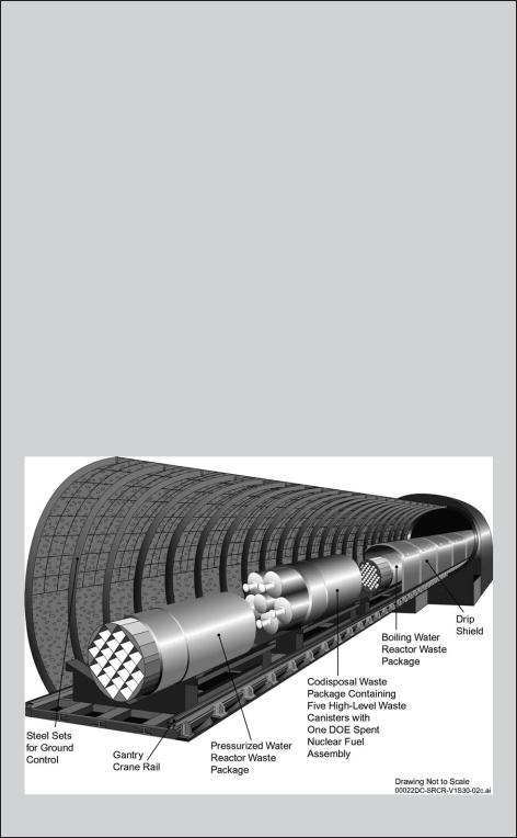
Original regulations specified that compliance with safety guidelines had to be assured for only 10 thousand years and hence, despite such surprises, it was possible to build a safety case by developing a design with sophisticated (and expensive) engineered barriers. This includes use of special high performance steel packages and titanium drip shields which are unique to this concept (see Figure, below). At present, however, the short compliance timescale has been questioned and periods of up to a million years are now being considered (Herbert, 2005; NW, 2005). The entire fundamentals of the safety concept now have to be reassessed to determine if a viable project at this location can be developed.
Figure: Current Yucca Mountain EBS design
Development of geological disposal concepts |
51 |
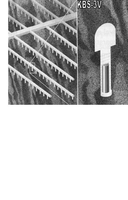
Fig. 3.6. The original KBS-3 disposal concept, now termed KBS-3V (Image courtesy of SKB).
the crystalline basement of northern Switzerland – amongst other reasons due to opportunities for collaboration with the other countries studying this host rock at that time (Sweden, Finland, Canada, USA and the UK). This is overlain by sediments and upper parts are highly weathered, which resulted in a minimum depth being set as around 800 m. The maximum depth of around 1300 m was set by construction practicality (ambient rock temperature around 50LC). The original design specifications from the safety assessors called for temperatures of < 100LC in significant parts of the bentonite3, resulting in a design with a very thick backfill (sometimes termed ‘‘the buffer’’, but this usage is avoided here to minimise risk of confusion with the important chemical buffering roles played by several engineered and natural barriers – see section 3.3.3.3). This ruled out the SKB inhole emplacement process and resulted in a layout with horizontal emplacement in tunnels.
The original SKB design specified a 10 cm thick copper canister to encapsulate the SF. For mechanical stability, internal voids would be filled with lead. It was assumed that the copper is so inert under the in situ conditions that it will last effectively indefinitely
3 A better understanding of bentonite properties obtained since then indicates that bentonite temperatures of up to 150LC can be sustained for extended periods without significantly affecting the bentonite performance and this is now being reflected in more recent designs where either less bentonite backfill is used or the waste is emplaced at a higher density (e.g., Nagra, 2002a; NUMO, 2004).

52 |
I.G. McKinley et al. |
(NB this argument was supported by native copper found in some of the potential host rocks and calculated best estimates of corrosive penetration in 10–100 Ma).
Nagra selected a massive (25 cm thick walls) steel canister for vitrified waste because the deep groundwater chemistry (in particular, the higher sulphate content) in northern Switzerland was more aggressive to copper than in the Scandinavian Shield (NWGCT, 1984). In addition, a greater mechanical strength was required to withstand the high external pressure (up to a maximum of about 30 MPa) as the thin stainless steel fabrication flask containing the vitrified waste contains a void space. Such a design resulted in a canister robust enough to last for at least 1000 years, to ensure complete containment of the waste during the early thermal perturbations and hydraulic transients in the nearfield.
Although the original Nagra design reflected a predominantly engineering approach to the problems of containment, there were several very clear chemical advantages of this design (McKinley, 1985), namely:
massive redox (steel canister) and pH (bentonite) buffers ensuring low solubility of many of the key radionuclides present in the waste
colloid filtration due to the microporous nature of the compacted bentonite after resaturation
diffusive solute transport dominates over advection because of the extremely low hydraulic conductivity of the resaturated bentonite
high retardation of radionuclides in the buffer due to the good sorptive properties of the bentonite.
Recently, designs are more focused on practicality of implementation – a factor almost completely ignored in the early projects due to the assumption that technology could be developed to implement any specified option in a safe and quality assured manner. Experience gained in underground test sites has shown that such implementation is not a trivial task – particularly when it has to utilise remote-handling or teleoperational procedures. For the very low permeability Opalinus Clay currently being examined in Switzerland, the changed emplacement procedure (Nagra, 2002b) includes the use of bentonite granules which can be pumped into position around the waste package that is emplaced on a plinth of compacted bentonite blocks. This design modification results in a very much simpler, faster, and more robust emplacement process than any option involving placing large numbers of individual bentonite blocks (Fig. 3.7).
In Sweden, a major constraint on the practicality of the original KBS-3 design has been found to be the damp conditions to be expected in such a repository, which makes handling of compacted bentonite in any form problematic (cf. Huertas et al., 2000). Significant design changes include prefabrication of the overpack plus bentonite within a handling shell4 and a move to in-tunnel emplacement of such a module (e.g., SKB, 1992). Further work on this concept is ongoing in cooperation with Nagra, showing that exchange of ideas between these partners continues. As a further design modification driven by the practicalities of safe and efficient operation, SKB have been looking into the use of low pH grouts and concretes for sealing water-conducting fractures intercepted
4 This concept has been extensively studied over the last decade as a Swiss–Japanese collaborative project – e.g., McKinley et al. (2001).