


Development of geological disposal concepts |
65 |
programmes with small radwaste inventories. Here, some technical alternatives are presented in section 3.5.2 and an implementation variant, which may have an influence on the weighting of barriers, in section 3.5.3.
3.5.2. Alternative geological disposal concepts
3.5.2.1. Utilising existing underground facilities
This book focuses on deep geological disposal in specially designed and constructed repositories. A slight variation on this theme involves disposal in existing underground cavities – generally disused mines – particularly as an option for lower-activity/shorter- lived waste streams. Especially when compared to surface disposal options, this may provide a very cost-effective way of providing the higher levels of safety associated with deep disposal within a stable geological foundation. This option has already been implemented in several countries in the past (e.g., Czech Republic, Germany, Pakistan), but, in some cases, problems have been encountered which can be traced back to the incompatibility of the constraints on utilisation of resources in the mining industry with those when the geosphere is expected to play a barrier role.
A particular example involves utilisation of worked-out mines in evaporites. In cases where large excavated caverns already exist at depth and access infrastructure is in place, this provides an attractive option for easily and cheaply disposing of a wide variety of wastes6. The pros and cons of this particular option depend, however, very much on the geological setting, the history of mining activity and the type of waste being considered for disposal. Safety depends on the integrity of the evaporite body being maintained and this may be threatened by convergence of the underground voids created by mineral extraction. It will also be important to ensure that all access points to the host rock – including those created by exploration drilling – can be identified and adequately sealed. In this regard, the Morsleben case provides an illustration of potential problems (e.g., Storck et al., 2004); after decades of use for disposal of L/ILW, expensive decommissioning is underway following problems caused by water breakthrough as a result of previous mining activities.
Although not often considered at present (an exception is Konrad, in Germany; e.g., Kernenergie, 2006), there can be good arguments for considering rocks which have immobilised ore bodies (including U) for hundreds of millions of years as good potential hosts for radioactive wastes. As long as not significantly perturbed by mining, the geological (tectonic), geochemical and hydrogeological conditions which led to the preservation of an anomaly such as an ore body are the same as those which would be conducive to the isolation of radioactive waste (section 3.3). Indeed, such ore bodies have often been examined for precisely these reasons as natural analogues of the processes likely to occur in repositories over geological time (see Miller et al., 2000, for an overview and Alexander et al., 2006, for an example of a recently completed study).
This kind of analogue argument could, in fact, be used to support the safety case for the disposal site (see also Chapters 6 and 8). More pragmatically, the large efforts involved in site characterisation and construction and the availability of relevant surface infrastructure and a trained workforce may make strong economic and socio-political
6 Indeed, this option is already extensively used in Europe for disposal of a wide range of chemotoxic wastes.
66 |
I.G. McKinley et al. |
arguments for utilisation of such a location. In the case of an ore body which is worked out, there may be local acceptance of such an option to guarantee long-term employment. Nevertheless, the entire disposal concept would need to be analysed to the equivalent depth to that considered for conventional repositories. In addition, human intrusion scenarios may need special attention; the fact that an area has been mined indicates that it may be a target for future exploration activities, especially as the technology/economics of utilisation of lower ore quality improves.
3.5.2.2. Extended storage options (CARE)
Given the high weighting assigned to public acceptance, it might well be necessary (or desirable) to move away from a fundamental design constraint central to most conventional designs – i.e., that waste is sealed in place as quickly as possible. Such a constraint is based on very good technical justification, as a sealed disposal system is inherently more stable mechanically, hydrologically and geochemically and hence provides a better basis for assuring long-term safety. Any ‘‘monitoring’’ which is included in such designs must avoid perturbing the engineered barriers and hence, with present technology, cannot really measure any parameter relevant to long-term safety (see also comments in Chapter 10).
The lack of precedent for HLW disposal has, however, increasingly led to calls for slow, staged implementation which is monitored (or even inspectable) and easily reversible for a long institutional control period (see Chapter 7). To provide a disposal system which meets this requirement requires re-thinking the entire repository concept – but can result in some options which also have attractions from the viewpoint of long-term safety.
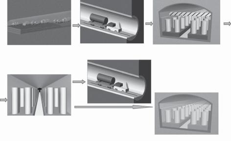
A concept developed to meet this requirement, termed ‘‘CARE’’ (CAvern Extended Storage), is illustrated in Fig. 3.10. In this, the basic components of a typical surface intermediate storage facility are implemented in a deep geological setting. Massive multipurpose (transport/storage/disposal) casks containing many HLW waste packages (typically around 20) are, possibly after a period of surface storage, transferred underground for a further long-term storage period (typically up to 300 years) – during which they are fully monitored and can be retrieved at any time. As opposed to very long-term surface storage options, however, when a decision is made to stop monitoring, the storage caverns can be simply backfilled to form a permanent disposal facility.
This option thus avoids many aspects of the ethical debate surrounding storage options which require subsequent final disposal facilities to be constructed by future generations. The long-term institutional control certainly raises issues associated with operational safety during this period (especially considering perturbations such as earthquakes, civil disturbances, etc.), but this design also has significant advantages due to its small footprint and, possibly, the long-term performance of the sealed system (see McKinley et al., 2004; Masuda et al., 2004 for details).
More recently, the CARE concept has received particular interest for the handling of spent fuel and other materials which are currently considered as waste, but may have future value as resources in the case of expanding long-term requirements for nuclear power (as mentioned previously in section 3.4.4). In this case, the option of being able to show a commitment towards providing the infrastructure for disposal now, yet maintaining the option to remove some or all of the material for long periods, is a clear advantage. Even if spent fuel is removed in the future for reuse, the underground caverns and infrastructure can be utilised for disposal of resulting reprocessing wastes.
Development of geological disposal concepts |
67 |
a) Construction |
b) Transportation |
c) Emplacement |
|
e) Option to remove |
|
|
some or all waste (figure |
|
|
to be modified) |
|
|
or |
|
d) Extended Storage |
|
|
(inspectable) |
|
|
|
f) |
Backfill and Sealing |
Fig. 3.10. CARE concept: (a) the caverns at a depth >300 m are accessed by a ramp and a number of shafts,
(b) the large transportation / storage / disposal casks are transported down the ramp by a road or rail system and emplaced upright (c) in large caverns with strong ventilation to remove radiogenic heat. During the storage period (d) waste is fully inspectable and can be easily retrieved at any time. After a decision is made to close the facility, caverns are backfilled and sealed (e).
3.5.2.3. Injection into deep aquifers and caverns
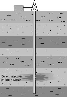
As a contrast to concepts utilising existing or specially constructed caverns, which may focus on a very high performance EBS, a variety of deep disposal options have been proposed in the past where the focus is placed predominantly on the geological barrier. Extreme examples include the direct injection of liquid radioactive waste into deep aquifers or of liquid radioactive waste/grout mixtures into hydrofractured rock (Fig. 3.11).
These options were extensively used in the past – in particular in the former Soviet Union (but also, e.g., at Oak Ridge in the USA; e.g., Byalko, 1992; NEDRA, 1992; Giere´ and Stille, 2004). Although considered acceptable under Cold War conditions, major operational and long-term safety concerns result from potential spillages of liquid waste and the difficulty of rigorously determining the location, form and long-term fate of the injected radionuclides. The requirements for use of multiple safety barriers and the difficulty in development of a robust long-term safety case mean that such approaches are no longer used in any national programme.
3.5.2.4. Deep boreholes
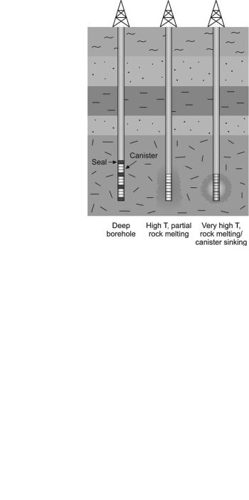
A series of less exotic alternatives to conventional repository designs involve waste emplacement in boreholes drilled from the surface (Fig. 3.12). Relatively shallow borehole emplacement of packaged waste is a well established practice for some lower toxicity/ shorter lived waste types (e.g., old radiation sources) and may be a cost-effective option where volumes of waste are small. Various designs for grids of deeper boreholes to emplace higher activity wastes have been examined as alternatives to conventional mined repository
68 |
I.G. McKinley et al. |
Fig. 3.11. Injection of liquid wastes or waste/grout mixtures into deep rock horizons.
approaches. Although possibly suitable for some particular rock/waste/geographical settings, there has, as yet, been no comprehensive evaluation of this option published (although several desk studies, concentrating on drilling technology aspects, have been documented over the last couple of decades; e.g., Nagra, 1980; SKB, 1992; Sizgek, 2001).
Very deep boreholes extend the geological disposal concept further, by emphasising the barrier role of the geosphere (Chapman and Gibb, 2003). At depths of several kilometres it is claimed that groundwaters are completely stagnant and hence waste can be emplaced without engineered barriers. Although variants of this concept appear in print on a regular basis, associated analyses tend to be superficial and emphasise the amount of R&D required in advance to assess viability (e.g., Nirex, 2005a). With increasing depth and waste activity, partial rock melting (see below) may also be included in the concept.
For all borehole disposal concepts, a practical concern is the possible jamming of waste packages in upper parts of the borehole. Even if the risk is low, it is very difficult to preclude such accidents entirely and resultant remediation could be extremely difficult and expensive. This leads to the development of concepts of shorter holes drilled underground – but these are already included in the ‘‘conventional’’ repository concepts (Chapter 5).
3.5.2.5. Rock melting
This can be considered a variant of other geological disposal options in which the liquid or solid waste is emplaced at high enough concentrations that radiogenic heat would be sufficient to cause partial or complete rock melting (Schneider and Platt, 1974). On eventual cooling of the molten rock, the wastes should be sealed by, or even completely
Development of geological disposal concepts |
69 |
Fig. 3.12. Several options for deep borehole emplacement of wastes.
incorporated into, the solid rock mass (the latter case being effectively a form of in situ SYNROC7). Specific design options include waste emplacement into excavated caverns at depth and ‘‘exploded cavities’’ – produced by nuclear explosives.
Evaluations of such concepts to date have been rather superficial and often concentrate on the properties of the solid product of waste and rock melting. Obvious concerns, which have not been examined in any detail, include:
Fate of important volatile radionuclides (e.g., 14C and 129I)
Response to/recovery from operational phase perturbations (especially those involving potential contamination of interim depth geological formations)
Quality assurance of the emplaced waste and associated requirements for monitoring
Rigorous modelling of the hydrothermal consequences of the imposed high temperatures
Requirements for site characterisation.
As noted above, such rock melting may be a component of deep borehole disposal options. One special variant of this may be worth mentioning – the super-dense waste package. In this design, very high waste loadings are incorporated in a dense, highly refractory waste matrix which is emplaced in a high integrity overpack. The package is emplaced in a deep borehole where temperatures become high enough to melt the
7 SYNROC or Synthetic Rock was an option originally proposed as a HLW matrix in the 1970s and is still under study in Australia, the USA and Russia (New Scientist, 2006). A review of SYNROC and a variety of other ‘‘mineral wasteforms’’ (and associated references) can be found in Miller et al. (2000; pp 94–97).