- •Introduction
- •1. Rectifiers
- •1.1 Employment, basic constituents
- •1.2. Technical and economic indexes of rectifier
- •1.3. Classification of rectifiers
- •1.4 Calculated basic parameters of designing
- •1.5 Some definitions
- •Thyristor as logical switch
- •1.7 A single-phase half-wave rectifier
- •1.7.1 Operation of single-phase half-wave rectifier with active load
- •For a secondary winding
- •For a primary winding
- •1.7.2. Operation of the half-wave rectifier with active - inductive load and limited inductance
- •1.7.3. Operation of the half-wave rectifier with resistive-capacitive load
- •1.8. A single-phase full-wave rectifier with a centre tap
- •1.8.1. Operation of a full-wave rectifier with a centre tap with an active load
- •1.7.2. Operation of a full-wave rectifier with centre tap and active - inductive load and limitеd inductance
- •1.8.3. Operation of a full-wave rectifier with centre tap and active - inductive load with infinite inductance
- •1.8.4. Consideration of a stage of switching of thyristors for a full-wave rectifier with centre tap and active - inductive load with infinite inductance
- •1.8.5 An external characteristic in per unit values
- •1 .9 A single-phase bridge rectifier
- •Figure 1.18
- •From cathode group thyristors current is flowing through that the right one witch have anode voltage greater than other one.
- •From anode group thyristors current is flowing through that the right one witch have cathode voltage less than other one.
- •1.10 The three-phase rectifier with a centre tap
- •1.10.3 The controlled three-phase circuit with a centre tap
- •1.10.4 The account of a stage of switching for three phase rectifier with centre tap
- •1.10.5 External characteristic
- •1.11 Three-phase bridge rectifier
- •The external characteristic
- •1.12 The double three-phase rectifier with balancing reactor
- •1.12.2. Definition of parameters for a choice of thyristors, calculation of the transformer and the balancing reactor
- •1.12.3 Merits and demerits, conditions of application
- •1.13 Equivalent polyphase circuits
- •1.13.2. Parallel connection of double three-phase bridge rectifiers
- •Average value of the rectified voltage is
- •1.14 Operation of the rectifier with opposite- emf
- •1.14.1. Operation of the half-wave rectifier with center tap with opposite- emf and active load
- •1.14.2. Operation of the half-wave rectifier with center tap and opposite-emf and active-inductive load
- •2. Dependent inverters
- •2.1 Transition from a rectifying conditions to an inverting conditions
- •External characteristics
- •3. Equipment and characteristics
- •3.1 Transformers for converting sets
- •3.2 The higher harmonics of a current and a voltage
- •The higher harmonics in a curve of the rectified voltage
- •3.2.3 The higher harmonics in a curve of a prime current
- •3.3. Power characteristics of the converter
- •3.3.1. Efficiency
- •3.3.2 Power factor
Thyristor as logical switch
Figure 1.3
Thyristor is been turning on, i.e. switch is been short-circuiting, when
uD()≥0 – voltage applied across thyristor is hit-crossing zero point to positive direction;
a control pulse is applied;
Thyristor is been turning off, i.e. switch is been disconnecting, when
- iT()0- anode current is hit-crossing zero point to negative direction.
1.7 A single-phase half-wave rectifier
Figure 1.4
1.7.1 Operation of single-phase half-wave rectifier with active load
Conditions: La = 0, Ld = 0, =0
id e2
UV
Rd
VS
iV
~ |
e i1
i1(1)
Id
Открыт
Закрыт
Ud
id
U1,
i1
Ud
2π
π
е2
0
0
0
0
id=i2=iV
e2m
Udm
Uобрm |
The a peak rectified current of the load and a peak thyristor current are
Direct component of a rectified voltage is
Direct component of rectified current and current of the thyristor are
RMS current of the thyristor is equaled to RMS current of a secondary winding of the transformer
A peak inverse voltage
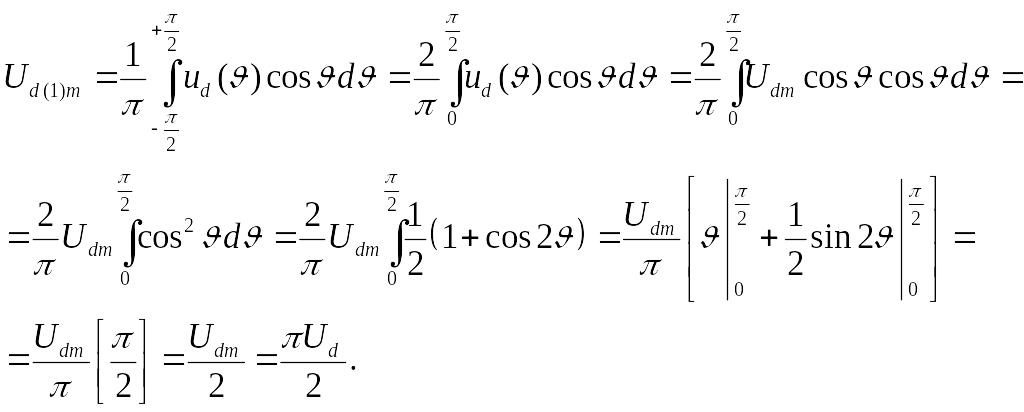
Let's define 1-th harmonic Ud and id
It is an even function.
Then
A RMS rectified voltage
A ripple factor of rectified voltage Ud for 1-th harmonic is
A ripple factor of rectified voltage Ud is
RMS value of EMF of secondary winding is
.
Instantaneous value of i1 we should define from a magnetic balance condition of the transformer by a variable component. Magnetic voltage drop is not taken into account. The direct component is not transferred into a primary winding.
Then
Let’s define rms value of i1
Let’s define the total powers of the transformer’s windings.
For a secondary winding
where Pd – the power of direct components of rectified voltage Ud and rectified current Id.
For a primary winding
Type power or electrical rating is
Active power of a rectified current is
,
i.e. Pad is approximately 2,5 times greater than Pd. That is the reason of increasing of the transformer. In the core of the transformer is created the additional permanent magnetic flux penetrating the core due to a constant component of a secondary winding current. This phenomenon is named as the permanent magnetization of the transformer. As a result the magnetizing current grows up by a few times. So it is necessary to increase sections of a wire of a primary winding and the dimensions of the transformer at whole. It is also necessary to increase the dimensions of the transformer thanks availability of higher harmonics at primary current.