
- •Introduction
- •1. Rectifiers
- •1.1 Employment, basic constituents
- •1.2. Technical and economic indexes of rectifier
- •1.3. Classification of rectifiers
- •1.4 Calculated basic parameters of designing
- •1.5 Some definitions
- •Thyristor as logical switch
- •1.7 A single-phase half-wave rectifier
- •1.7.1 Operation of single-phase half-wave rectifier with active load
- •For a secondary winding
- •For a primary winding
- •1.7.2. Operation of the half-wave rectifier with active - inductive load and limited inductance
- •1.7.3. Operation of the half-wave rectifier with resistive-capacitive load
- •1.8. A single-phase full-wave rectifier with a centre tap
- •1.8.1. Operation of a full-wave rectifier with a centre tap with an active load
- •1.7.2. Operation of a full-wave rectifier with centre tap and active - inductive load and limitеd inductance
- •1.8.3. Operation of a full-wave rectifier with centre tap and active - inductive load with infinite inductance
- •1.8.4. Consideration of a stage of switching of thyristors for a full-wave rectifier with centre tap and active - inductive load with infinite inductance
- •1.8.5 An external characteristic in per unit values
- •1 .9 A single-phase bridge rectifier
- •Figure 1.18
- •From cathode group thyristors current is flowing through that the right one witch have anode voltage greater than other one.
- •From anode group thyristors current is flowing through that the right one witch have cathode voltage less than other one.
- •1.10 The three-phase rectifier with a centre tap
- •1.10.3 The controlled three-phase circuit with a centre tap
- •1.10.4 The account of a stage of switching for three phase rectifier with centre tap
- •1.10.5 External characteristic
- •1.11 Three-phase bridge rectifier
- •The external characteristic
- •1.12 The double three-phase rectifier with balancing reactor
- •1.12.2. Definition of parameters for a choice of thyristors, calculation of the transformer and the balancing reactor
- •1.12.3 Merits and demerits, conditions of application
- •1.13 Equivalent polyphase circuits
- •1.13.2. Parallel connection of double three-phase bridge rectifiers
- •Average value of the rectified voltage is
- •1.14 Operation of the rectifier with opposite- emf
- •1.14.1. Operation of the half-wave rectifier with center tap with opposite- emf and active load
- •1.14.2. Operation of the half-wave rectifier with center tap and opposite-emf and active-inductive load
- •2. Dependent inverters
- •2.1 Transition from a rectifying conditions to an inverting conditions
- •External characteristics
- •3. Equipment and characteristics
- •3.1 Transformers for converting sets
- •3.2 The higher harmonics of a current and a voltage
- •The higher harmonics in a curve of the rectified voltage
- •3.2.3 The higher harmonics in a curve of a prime current
- •3.3. Power characteristics of the converter
- •3.3.1. Efficiency
- •3.3.2 Power factor
3.2 The higher harmonics of a current and a voltage
The higher harmonics in a curve of the rectified voltage
ud
Um
α
α


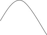
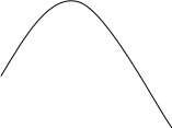


![]()


Figure 3.1
ud = Ud-+ ud ~.
For all circuits of rectifying and inverting at Ld = ∞ and no-load (without taking into account losses)
![]()

where ω1 = ωm ,
ω -a line frequency,
ω1 - frequency of 1-th harmonic of a rectified voltage,
m - a multiplicity of pulsations ud,
n - the order of a higher harmonic,
Unm - amplitude of the higher harmonic about n,
n - an initial phase of the higher harmonic about n.
Then
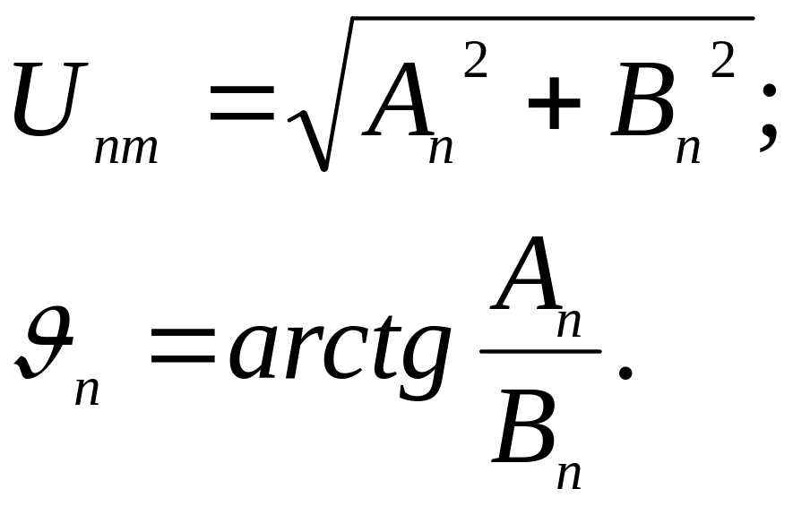
Amplitude cosine component

Amplitude sine component

Period of the first harmonic of the rectified voltage
![]()
The rectified voltage we is described by function
![]()
For single-phase half-wave, single-phase full-wave with centre tap, a single-phase bridge, three-phase zero circuits
![]()
For a three-phase bridge
![]()
For the circuit of a double three-phase star with the current-balancing reactor
![]()
Then


From here

In per units

With increase fast growth of the higher harmonics would be observed.
3.2.3 The higher harmonics in a curve of a prime current
If Pd there is less than power of supply network, rectifier influence to supply network can be not taken into account, U1 practically is not distorted. If Pd is commensurable with power of the supply network SNW, the higher harmonics of a current will create a voltage drop across supply network reactances witch is proportional to order of the higher harmonic and U1 will be deformed. In this case it is necessary to apply filters.
The order of the higher harmonics of a prime current is
![]() ,
,
where К=1,2,3…
m - a multiplicity of pulsation of Ud.
If γ=0 Ld=∞ and (i.e. the form of i1 is graduated),
![]()
where I1(q) - a rms current of q-th harmonic,
I1 (1) - a rms current of 1-st harmonic.
3.3. Power characteristics of the converter
3.3.1. Efficiency
Active losses of a converter are
1) The thyristor losses ∆РT.
2) The transformer losses
∆РTr = ∆РSt+ ∆РCop,
where ∆РSt - steel losses;
∆РCop - Cop-losses in windings.
3) The reactors losses ∆РR (anodic, smoothing and current-balancing).
4) Losses in the auxiliary equipment (a control and regulation system, cooling system) ∆PAux.
∆РSt and ∆РAux are constant and are not load-depending.
For middle-and high-voltage sets
![]()
where m - number of thyristors in the circuit,
∆UT - a voltage drop on the thyristor.
More precisely if to take into account current-voltage diagrams of the thyristor
U0
ctg α =
RД
α
UV
iV


where kf - the form factor.
Then, for low-voltage rectifiers
![]()
Primary windings of the transformer losses
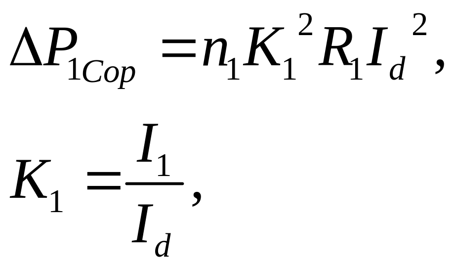
where n1 - number of primary windings,
R1 - resistance of a primary winding.
Secondary windings losses the transformer
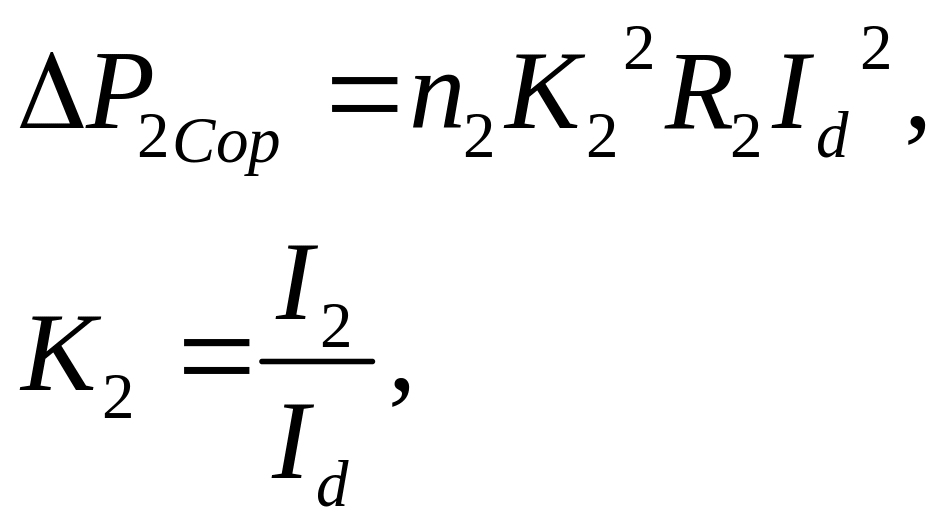
where n2 - number of secondary windings;
R2 - resistance of secondary windings.
Reactor losses
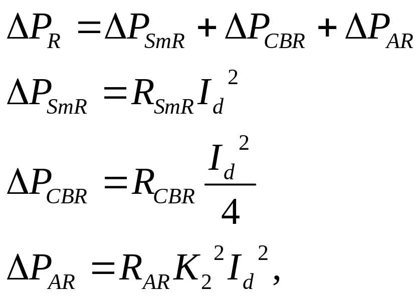
where ∆РSmR – the smoothing reactor losses,
∆РCBR - the current-balancing reactor losses,
∆РAR - the anodic reactor losses.
The core of reactors losses , as a rule, do not take into account.
Thus, at Ld≈∞
![]()
At Ld <∞ it is necessary to add a addendum into a denominator
![]()
For converters of low power
![]()
where ηTh – thyristor block efficiency,
ηTr - transformer efficiency,
ηf – filter efficiency.
