

External characteristics
Udα
δ > 0
δ = 0
II
α = 1200
β = 600
α = 900
β = 900
α = 0
α = 600
I
Id


Ограничительная характеристика
Figure 2.3
I - a rectifier conditions;
II - inverter condition;
ΔUx has the as same sing as a no-load voltage.
As
![]()
then in case
δ=0 will be β=γ.
The range of a modification β is limited by an angle δ, allowable by the given type of a thyristor.
βmin = δ0 + γ,
when δ0 - classification parameter for the given type of a thyristor.
Usually δ0 = 0.2 degree at f c= 50 Hz.
Principle of operation for more complex inverter’s schemes is one and the same. Consequently, all circuits of the rectifying may be used for a current inverting. For this purpose it is necessary to change a sign opposite - EMF and a commutation delay angle to make more than 90 degrees .
All equations of dependences Id = f(α, γ, Xа) and an external characteristics Udα =f(Id ) of rectifiers are fair to dependent inverters if to replace on α to π-β.
Then for the considered scheme
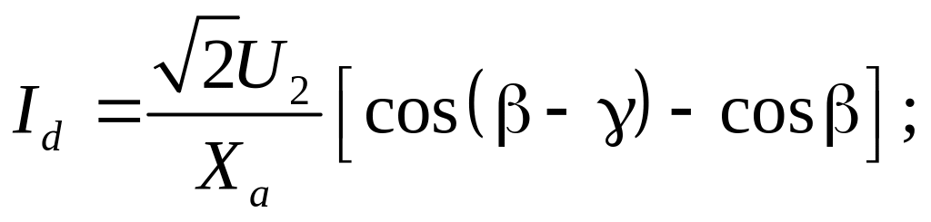
![]()
The same one is for other circuits of rectifying and inverting.
The dependent inverters are widely applied for an electrical haulage, for the electric drive to braking DC for current recuperation to a supply network, for the electric drive of an alternating current by the rectifier cascade scheme, for systems of DC power lines etc.
3. Equipment and characteristics
3.1 Transformers for converting sets
Functions of transformers:
- Transformation of magnitude of voltage;
- A galvanic outcome (the power circuit are separated from a circuit of a load);
- Transformation of phase number of a voltages system;
- Shift of phases of primary and secondary voltages.
The operating conditions of a transformer for converter differ from the operating conditions of transformers for linear load and standard frequency in 50 Hz.
The nonlinear loads are a reason of nonlinear currents through windings of the transformer and nonlinear magnetic fluxes in a core. The heightened frequency causes additional losses in the core and windings.
Constructive differences:
- Owing to heavier emergency operation it is necessary to augment inductance of windings for limitation of emergency currents, and also safely to fix windings and core for the reason that dangerous electrodynamic forces arise at emergencies;
- For series of schemes a total power of secondary windings S2 is greater than a total power of primary windings S1;
The dispersed magnetic fluxes essentially influence to character of electromagnetic processes
in the converter. They determine inductive reactance of dispersion Хs, which, in basic, is determined by inductance La). The character of distribution of dispersed magnetic fluxes depends on a core shape, type and windings disposition each from other, their construction, etc.
The resistance of windings is determined ra.
For low power converters ra >> Хa and dispersed fluxes is neglected at such convertersdesigning.
For
high-power converters there are Ха
>>
ra
(as a rule,
![]() ),
and ra
is
neglected, but commutation stage of rectifiers influences to a marked
degree to operation and converters designing.
),
and ra
is
neglected, but commutation stage of rectifiers influences to a marked
degree to operation and converters designing.
For converters of average power it is necessary to take into account as ra as Ха.
There are two types of transformers for rectifiers and dependent invertors.
1) The transformer for the single-cycle schemes (half-wave, three-phase zero, full-wave three phase with LR), where exists direct -current component of a secondary winding, and for compensation of a forced magnetization flux it is necessary to arrange two secondary windings on a same rod (for example, "«zigzag" for a zero scheme). For an identical disposition of secondary windings in relation to primary they execute as rigid each other winded spirals, that the dispersed fluxes between secondary windings would be minimum ones.
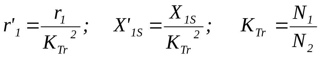
2) The transformer for the two-stroke schemes differs from usual only by higher values Хs (single-phase and three-phase bridge-schemes). At compiling equivalent circuits of resistance of a primary winding reduce to secondary, because parameters of a load Id and Ud are data for calculation of converter.
![]()
where r '1 -active resistance reduced to a secondary winding from a primary winding,
r2 - active resistance of a secondary winding.
Ха = Х ' 1S+X2S,
where Х ' 1S - dispersed inductance of a primary winding reduced to a secondary winding ,
X2S - dispersed inductance of a secondary winding.
The parameters of the equivalent schemes of the transformer define by practical consideration with the help of experiences short circuit and open-circuit conditions.