

imit_model / AnyLogic / UsersManual(AnyLogic)
.pdfAnyLogic V User’s Manual
►To zoom in on the diagram to fit all shapes
1.Choose Draw|Zoom|Zoom to Fit from the main menu, or
Right-click the the empty area of the diagram and choose Zoom to Fit from the popup menu.
The diagram will be centered and zoomed to fit all the shapes.
►To zoom in
1.Click the Zoom In  toolbar button, or
Choose Draw|Zoom|Zoom In from the main menu.
►To zoom out
1.Click the Zoom Out  toolbar button, or
Choose Draw|Zoom|Zoom Out from the main menu.
►To zoom to the specified rectangle
1.Choose Draw|Zoom|Zoom to Rectangle from the main menu.
2.Drag the selection rectangle around the area you want to zoom to.
►To zoom to the default scale
1.Choose Draw|Zoom|Zoom to Default from the main menu.
You can control the diagram grid appearance.
►To enable/disable the grid
1.Click the Enable Grid  toolbar button, or
Choose Draw|Grid|Enable Grid from the main menu.
►To show/hide the grid
1.Choose Draw|Grid|Show Grid from the main menu.
© 1992-2004 XJ Technologies http://www.xjtek.com |
27 |

Chapter 1. Creating AnyLogic model
►To snap a shape to the grid
1.Select the shape.
2.Click the Snap to Grid  toolbar button, or
Choose Draw|Grid|Snap to Grid from the main menu.
By default, when you resize, drag, or move a shape, other shapes logically related to it also move. For example, connectors move with ports, encapsulated objects move with this object, simple states reflect changes of the composite state, etc. Sometimes this is undesirable, so you always can switch smart dragging off.
►To switch smart dragging off during the operation
1.Hold Shift while finishing the operation.
►To edit the name of a shape
1.Double-click the name of the shape, or
Right-click the shape and choose Edit Name from the popup menu, or Press F2.
2.Type the name of the shape.
3.Press Enter or click the empty area of the diagram to store the modified name, or Press Esc to cancel editing.
The name of a shape can also be edited in the Properties window.
►To rotate a shape
1.Click the Rotate  toolbar button, or Choose Draw|Rotate from the main menu.
2.Use rotation handles to rotate a structure element.
►To get compact information on shape properties
1.Point mouse cursor at the shape and wait for tooltip to appear.
28 |
© 1992-2004 XJ Technologies http://www.xjtek.com |
AnyLogic V User’s Manual
1.5.3Active object icon
Each active object class may have specific icon associated with it. Each time an instance appears as an encapsulated object on a structure diagram, or on animated structure diagram (see section 11.2.2, “Animated structure diagram”), this icon is displayed. Note that this image has nothing to do with AnyLogic animation and is not displayed on the structure diagram of this active object class itself.
1.5.3.1 Icon diagram
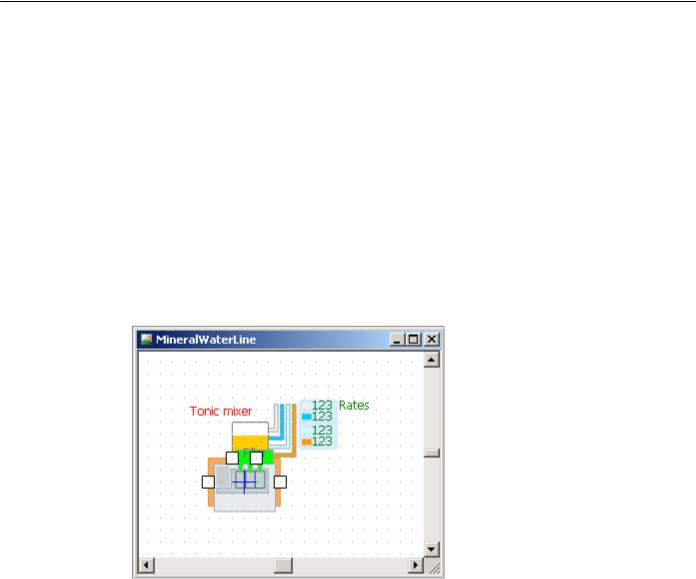
The active object icon is defined on the icon diagram. An icon diagram is edited in the icon editor (Figure 8) using the animation toolbar.
Figure 8. Icon editor
►To create an icon for an active object class
1.Click the New Icon  toolbar button, or Choose Insert|New Icon… from the main menu. The New Icon dialog box is displayed.
Specify the name of the new icon, choose the active object class, which will contain the icon, and click OK.
© 1992-2004 XJ Technologies http://www.xjtek.com |
29 |
Chapter 1. Creating AnyLogic model
2.Alternatively, in the Project window, right-click the active object class, which will contain the icon, and choose New Icon… from the popup menu.
The New Icon dialog box is displayed.
Specify the name of the new icon and click OK.
3.The icon editor window is displayed.
Each active object class may have only one associated icon.
► To open the existing icon of an active object class
1.Right-click the Icon item of the active object class in the Project window and choose Open Icon from the popup menu.
The icon editor window is displayed.
Icon editor shares a set of generic editing operations described in section 1.5.2, “Diagram editors. Generic operations”.
The blue cross is the origin point (0, 0) of the icon diagram.
An icon is a drawing composed of various shapes: circles, rectangles, lines, etc., and also indicators. You can construct your icon from any animation shapes and animation indicators. See section 12.2.2, “Animation shapes” and section 12.2.3, “Indicators” for the detailed description of these shapes. The icon size is set automatically to fit all the shapes.
Each shape has a number of properties defining its visual appearance: position, height, width, color, and so on. The generic properties of the shapes are described in section 12.2.1.2, “Generic properties of animation shapes”.
1.5.3.2 Icon animation concepts
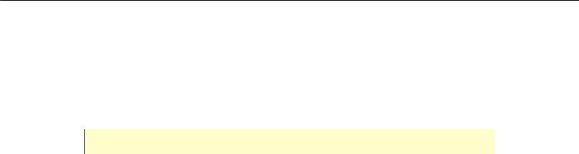
Each shape has a number of properties defining its visual appearance: position, height, width, color, and so on. These properties are typically organized as shown in Figure 9:
30 |
© 1992-2004 XJ Technologies http://www.xjtek.com |

AnyLogic V User’s Manual
Name of the property
Constant corresponding to the |
|
Expression defining the actual |
value in the editor (default) |
|
value during simulation |
|
|
|
Figure 9. Property of an icon shape
The concepts are similar to the AnyLogic animation concepts – icon diagram links shape properties to active object data.
The static value on the left shows the value of the property as defined while drawing in the editor. It is also treated as a default value. The expression on the right defines the actual value during simulation. This is the place where you can link the appearance of a shape to any data of the active object. The data may change and it will be reflected in the picture. In case the expression is empty, the property retains the default static value throughout the whole simulation.
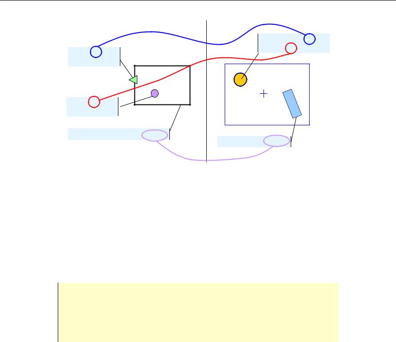
An example of associating graphical properties of icon shapes with active object data is shown in Figure 10. Here the coordinates of the circle are dynamically defined by the variables x and y of the active object, and the rotation angle of the rectangle is defined by the object member variable alpha.
© 1992-2004 XJ Technologies http://www.xjtek.com |
31 |
Chapter 1. Creating AnyLogic model
Model Icon
X: -60 | 10 * x Y: -35 | y + 43.8
Name: x
Type: double
Name: y
Type: double
Additional class code: int alpha;
Rotation: 338 | alpha
Figure 10. Associating graphical properties with model data
Thus, by linking shape properties to active object data, you can animate active objects on the animated structure diagram at the model runtime.
1.5.3.3 Active object image
Active object icon is the new feature of AnyLogic V. In the previous versions of AnyLogic, you could only associate a static image loaded from file, with an active object class.
In fact, active object image feature is left for compatibility with the previous versions only. It is recommended that you create an icon for an active object class and add an image shape to this icon instead of using active object image. Note that the image of an active object class is suppressed with the icon of this active object, if the latter is defined.
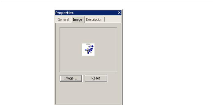
Active object image is defined on the Image page of the active object’s Properties window (see Figure 11).
32 |
© 1992-2004 XJ Technologies http://www.xjtek.com |
AnyLogic V User’s Manual
Figure 11. Image page of active object’s Properties window
►To define an image for an active object class
1.Click the active object class in the Project window.
2.Click the Image button on the Image page of the Properties window.
The Choose Image dialog box is displayed. The dialog displays the predefined images.
3.To use one of predefined images, Double-click the image, or
Click the image and click OK.
4.Otherwise, to load the image from file, Click the Browse button.
The Open dialog box is displayed.
Browse for the image file you want to use. Double-click the file, or
Click the file and click Open button to select the file.
The specified image is shown on the Image page of the Properties window.
© 1992-2004 XJ Technologies http://www.xjtek.com |
33 |

Chapter 1. Creating AnyLogic model
►To remove the specified active object image
1.Click the active object class in the Project window.
2.Click the Reset button on the Image page of the Properties window.
1.5.4Encapsulated objects
Active objects may encapsulate other active objects to any desired depth. Encapsulated objects are instances of other active object classes, encapsulated by each instance of this active object class. Encapsulating a class is the step to create the model hierarchy.
►To add an encapsulated object to an active object class
1.Drag the active object class from the Project window onto the structure diagram of the parent active object class.
All encapsulated objects should be placed inside this object shape if the latter is present.
Encapsulated objects are displayed as filled rectangles (see Figure 12). In case AnyLogic cannot find the referred class, the encapsulated object is displayed red.
Encapsulated |
object A |
object |
|
Replicated |
object B* |
encapsulated object |
Figure 12. Encapsulated objects
Encapsulated objects have the following properties.
Properties
Name – name of the encapsulated object.
34 |
© 1992-2004 XJ Technologies http://www.xjtek.com |

AnyLogic V User’s Manual
Type – [read only] class of the encapsulated object.
Parameters – [optional] set of actual parameters of the encapsulated object. Every parameter should be given in form: Name Value, where Name is the name of the parameter, Value is the value of the parameter.
Exclude from build – if set, the encapsulated object is excluded from the model.
Show name – if set, the name of the encapsulated object is shown on the structure diagram.
Auto create – if set, AnyLogic creates the encapsulated object automatically. Otherwise the object should be created manually.
You can open the structure diagram of an encapsulated object class.
► To open the structure diagram of an encapsulated object
1.Double-click the encapsulated object, or
Right-click the encapsulated object and choose Open Structure from the popup menu.
If needed, you can flip an encapsulated object image on the structure diagram.
►To flip an encapsulated object horizontally
1.Select the encapsulated object.
2.Click the Flip Horizontal  toolbar button, or
Right-click the encapsulated object on the structure diagram and choose Flip Horizontal from the popup menu, or
Choose Draw|Flip Horizontal from the main menu.
Encapsulated objects can be single or replicated (do not confuse this with model replications). A replicated object represents a collection of active objects of the same class. Object replication provides for very economical representation of complex structures of objects with arbitrary interconnections. Replicated object name displayed on the structure diagram of the parent class is followed with an asterisk (see Figure 12). See Chapter 2, “Replicated objects” for the detailed description of replicated objects.
© 1992-2004 XJ Technologies http://www.xjtek.com |
35 |
Chapter 1. Creating AnyLogic model
1.5.5Root object
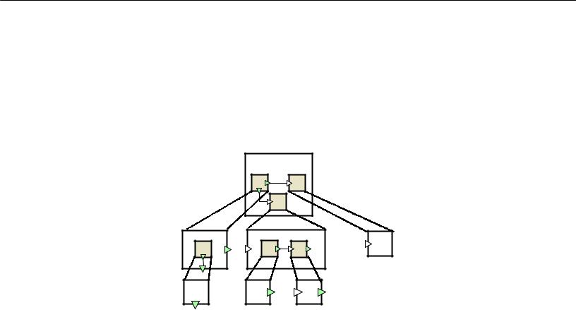
An AnyLogic model is a tree of active objects encapsulating each other (see Figure 13). Thus a model is decomposed into several levels of detail, since each active object typically represents a logical section of the model. The root of that tree is called the root object. The root object represents the highest abstraction level of your model. When you specify the class of the root object, you tell AnyLogic where to start the model creation.
Root object |
Figure 13. Tree of active objects
AnyLogic supports easy model modification since you can change the root object of a model. You can create several experiments with different root objects in the same project. Thus you can simply adjust your model structure by changing current experiments.
►To set a root object for an experiment
1.Click the experiment in the Project window.
2.In the Properties window, select the root object of the experiment from the Root object drop-down list.
For example, you model an automobile. You define the Automobile class and set this class to be the root object class since it represents the highest abstraction level of your model. This class encapsulates objects representing parts of the automobile: wheels, engines, carburetors, etc. They, in turn, may encapsulate objects representing their parts, and so on. However, you may need to focus on the automobile engine. Therefore you can simply set
36 |
© 1992-2004 XJ Technologies http://www.xjtek.com |