

imit_model / AnyLogic / UsersManual(AnyLogic)
.pdfAnyLogic V User’s Manual
1.4.2Package
A project consists of packages. There may be one or more packages in the project. Packages contain active objects, messages, other classes, and external files. Packages may be used for better structuring of a project.
►To add a new package to the project
1.Choose Insert|New Package… from the main menu, or
In the Project window, right-click the project and choose New Package… from the popup menu.
The New Package dialog box is displayed.
2.Specify the name of the new package and click OK.
Properties
Name – name of the package.
Exclude from build – if set, the package is excluded from the model.
When AnyLogic generates code, it maps every AnyLogic package to a Java package with the same name. As a result, classes in different AnyLogic packages are put into different Java packages. The rules of using AnyLogic packages are the same as rules of using Java packages. To use a class from another package, you have to import that package or prefix the name of the class with the name of the package. Package import is described in section 1.5.9.1, “Importing packages”.
If you do not want to deal with namespaces, you may use just one package in your project — e.g., mypackage. By default, when you create a new project, AnyLogic creates one package with the same name as the project name.
1.4.3Library
A project may use other projects as libraries. Libraries are collections of classes developed for some particular application area or modeling task. Several libraries come with the tool, and you can easily create your own.
© 1992-2004 XJ Technologies http://www.xjtek.com |
17 |

Chapter 1. Creating AnyLogic model
Libraries have several benefits:
•Provide for better reuse of classes across multiple models. A class can be developed and stored once and referenced from several projects.
•Libraries enable you to organize teamwork in AnyLogic projects: a part of the model developed by a team member may be put into a library, and others use consistent versions of the library in their work.
•By developing the right library you can convert AnyLogic into a high-level modeling tool with point-and-click interface for a specific domain.
AnyLogic shows available libraries in the Libraries window. AnyLogic standard distribution includes several libraries located in the Lib directory. Have a look at these libraries to get an idea of how to develop your own. The detailed information on creating libraries and using AnyLogic libraries classes is given in Chapter 19, “Libraries and external files”.
1.4.4Experiment
An AnyLogic experiment defines the type of experiment you want to carry out with your model. AnyLogic supports the following types of experiments:
• Simulation experiment
Simulation experiment is used in most cases. It runs model simulation with animation displayed and model debugging enabled. Running a model simulation is described in Chapter 11, “Running and observing a model”. Other AnyLogic experiments are used only when the model parameters play a significant role and you need to analyze how they affect the model behavior, or when you want to find optimal parameters of your model.
• Optimization experiment
If you need to run a simulation and observe system behavior under certain conditions, as well as improve system performance - for example, by making decisions about system parameters and/or structure - you can use the optimization capability of AnyLogic. Optimization is the process of finding the optimal combination of conditions that results in the best possible solution. Optimization is described in details in Chapter 16, “Optimization”.
• Custom experiment
18 |
© 1992-2004 XJ Technologies http://www.xjtek.com |

AnyLogic V User’s Manual
Allows defining a custom experiment script using Java language.
Experiment has a set of parameters you can adjust to configure model simulation (simulation time mode, number of model runs, simulation stop conditions, etc.). Setting up simulation parameters is discussed in Chapter 13, “Simulation settings”.
When a new project is created, a simulation experiment is created and set as the current experiment. The current experiment defines simulation parameters actual for the current simulation.
You can simply customize model simulation by creating several experiments with different simulation parameters set up and simulating your model with different current experiments. For instance, you may need to execute your model with different values of the root object parameters. Thus you create several simulation experiments with different parameter values specified and simulate your model with different experiments set as current.
►To create a new experiment
1.Click the New Experiment  toolbar button, or
Choose Insert|New Experiment… from the main menu, or
In the Project window, right-click the Experiments item and choose New Experiment… from the popup menu.
The Create a new experiment dialog box is displayed.
2.Choose the desired type of the experiment in the group box.
3.Type the experiment name in the Name edit box.
4.Select the root object of the experiment from the Root object drop-down list.
5.Click OK.
In the Project window, experiments are stored in the Experiments subtree of the workspace tree, located under the project item.
►To set an experiment to be a current experiment
1.Right-click the experiment in the Project window and choose Set as Current from the popup menu.
The current experiment name is emphasized in the Project window with bold.
© 1992-2004 XJ Technologies http://www.xjtek.com |
19 |

Chapter 1. Creating AnyLogic model
1.5 Active object
Active objects are the main building blocks of AnyLogic model. Active objects can be used to model very diverse objects of the real world: processing stations, resources, people, hardware, physical objects, controllers, etc.
An active object is an instance of an active object class. Active objects classes are developed by the user, or they can be taken from libraries.
►To add a new active object class to a package
1.Click the New Active Object Class  toolbar button, or Choose Insert|New Active Object Class… from the main menu. The New Active Object Class dialog box is displayed.
Specify the name of the new active object class, choose the package, which will contain the active object class, and click OK.
2.Alternatively, in the Project window, right-click the package, which will contain the active object class, and choose New Active Object Class… from the popup menu. The New Active Object Class dialog box is displayed.
Specify the name of the new active object class and click OK.
Each active object class has the following properties:
Properties
Class name – name of the class.
Base class – [optional] name of the base class. This can be ActiveObject or its subclass. If not specified, ActiveObject is assumed. See section 1.5.10, “Active object inheritance” for information on active object inheritance.
Parameters – [optional] a set of formal parameters of the active object class (see Chapter 3, “Parameters”).
Exclude from build – if set, the class is excluded from the project.
Show name – if set, the name of the class is shown on its structure diagram.
Show object rectangle – if set, the rectangle representing the border of this object is shown on its structure diagram.
20 |
© 1992-2004 XJ Technologies http://www.xjtek.com |
AnyLogic V User’s Manual
Public (exported from library) – if reset, in case this project is used as a library, this class is not accessible from other projects (you may need this to hide some auxiliary library classes).
1.5.1Structure diagram
Each active object class has a structure diagram associated with it. The structure diagram plays several roles. It:
•Defines the interface of the active object class
•Defines the encapsulated objects and their interconnection
•Defines behavior elements, such as timers and statecharts.
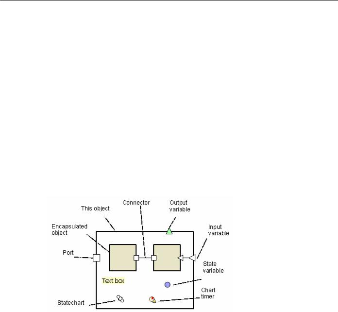
The structure diagram is constructed of various shapes, namely: this object, encapsulated object, port, variable, connector, chart timer, statechart, and text box (see Figure 6).
Figure 6. Structure diagram
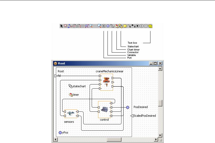
The structure diagram of an active object is edited in the structure editor using the structure toolbar (see Figure 7).
© 1992-2004 XJ Technologies http://www.xjtek.com |
21 |
Chapter 1. Creating AnyLogic model
Structure editor
Figure 7. Structure editor and toolbar
► To open the structure diagram of an active object class
1.Right-click the active object class in the Project window and choose Open Structure from the popup menu, or
Double-click the active object class in the Project window.
This active object is displayed as a bold frame. It denotes the “border” of the active object on its structure diagram. The semantics of this shape is that all ports and variables placed on it become interface elements of the active object class. This shape is optional on the diagram. The properties of this shape are actually the properties of the active object class.
22 |
© 1992-2004 XJ Technologies http://www.xjtek.com |

AnyLogic V User’s Manual
You can put a comment on a diagram using a text box. This does not affect the model behavior.
►To add a text box
1.Click the Text Box  toolbar button, or Choose Draw|Text Box from the main menu.
2.Click the place on the diagram where you want to put the text box. Then drag to choose the size of the shape.
►To modify the content of a text box
1.Double-click the text box.
2.Edit the content of the text box.
3.Click the empty area of the diagram or press Esc to store the modified text. You can also modify the text of the text box using its Properties window.
1.5.2Diagram editors. Generic operations
AnyLogic includes four diagram editors: structure editor, statechart editor, animation editor and 3D animation editor. They all are based on the same technology and therefore share a large set of generic editing operations described in this section. The specific operations are described in section 1.5.1, “Structure diagram”, section 9.2, “Statechart diagram”, section 12.2, “Animation diagram” and section 12.3, “3D animation diagram” correspondingly.
AnyLogic diagrams are constructed of graphical objects – shapes. To draw a shape, you click the corresponding toolbar button and place the shape on the diagram. Each editor has an associated toolbar with shapes specific for its diagram type.
Selecting shapes
You can select any shape on a diagram. When you select a shape, the Properties window displays its properties.
© 1992-2004 XJ Technologies http://www.xjtek.com |
23 |

Chapter 1. Creating AnyLogic model
►To select a shape
1.Click the shape.
►To select more than one shape
1.Drag the selection rectangle around the shapes.
►To add/remove a shape to/from the selection
1.Shift-click the shape.
►To select all shapes on the diagram
1.Choose Edit|Select All from the main menu, or Press Ctrl+A.
Copying, moving and deleting shapes
You can copy, move and delete shapes.
►To copy the selection on the Clipboard
1.Click the Copy  toolbar button, or Choose Edit|Copy from the main menu, or
Right-click the selection and choose Copy from the popup menu, or Press Ctrl+Ins.
►To cut the selection
1.Click the Cut  toolbar button, or Choose Edit|Cut from the main menu, or
Right-click the selection and choose Cut from the popup menu, or Press Shift+Del.
24 |
© 1992-2004 XJ Technologies http://www.xjtek.com |

AnyLogic V User’s Manual
►To paste the content of the Clipboard
1.Click the Paste  toolbar button, or Choose Edit|Paste from the main menu, or
Right-click the empty area of the diagram and choose Paste from the popup menu, or
Press Shift+Ins.
The pasted shapes appear in blue outline.
2.Move the pasted shapes to the desired position.
►To copy the selection
1.Ctrl-drag the selection.
►To move the selection
1.Drag the selection, or Use arrow keys.
►To delete the selection
1.Click the Delete  toolbar button, or Choose Edit|Delete from the main menu, or
Right-click the selection and choose Delete from the popup menu, or Press Del.
►To hide the selection
1.Choose Draw|Hide from the main menu.
►To unhide all hidden shapes
1.Choose Draw|Unhide All from the main menu.
© 1992-2004 XJ Technologies http://www.xjtek.com |
25 |

Chapter 1. Creating AnyLogic model
► To get the image of the whole diagram on the Clipboard
1.Choose Draw|Copy Image from the main menu, or
Right-click the empty area of the diagram and choose Copy Image from the popup menu.
You can undo previously performed actions.
►To undo the previous action
1.Click the Undo  toolbar button, or Choose Edit|Undo from the main menu, or Press Alt+Backspace, or Ctrl+Z.
►To redo the previously undone action
1.Click the Redo  toolbar button, or Choose Edit|Redo from the main menu, or Press Ctrl+Y.
You can move, center, or zoom in on the diagram to take a good look at some particular parts of it.
►To move the diagram
1.Click on the diagram with the right mouse button and, while holding the right mouse button down, move the mouse.
►To center the diagram
1.Choose Draw|Go to Center from the main menu, or
Right-click the the empty area of the diagram and choose Go to Center from the popup menu.
The diagram will be centered.
26 |
© 1992-2004 XJ Technologies http://www.xjtek.com |