

imit_model / AnyLogic / UsersManual(AnyLogic)
.pdfAnyLogic V User’s Manual
EntityOutPortQueue class
The EntityOutPortQueue port class, derived from EntityOutPort, is used to model output ports with queues. This port is commonly used in entity processing objects. If more than 1000 entities are pending, the port signals an error.
The methods of the EntityOutPortQueue class are listed in Table 15.
Method |
Description |
|
|
void take() |
The method places the entity passed as the method |
|
parameter in the port queue. |
|
|
Entity getEntity() |
The method extracts the first entity from the port queue. |
|
|
boolean isEmpty() |
The method checks if there are any entities pending in the |
|
queue (the method returns false if there are any pending |
|
entities and true otherwise). |
|
|
void setCanWait(boolean |
The method allows or forbids the entity waiting at the |
cw) |
output port queue by passing true or false |
|
correspondingly. (However, multiple entities can be passed |
|
to an output as long as they all are passed further in zero |
|
time). |
|
|
int size() |
The method returns the number of pending entities. |
|
|
Table 15. EntityOutPortQueue class methods
© 1992-2004 XJ Technologies http://www.xjtek.com |
217 |
Chapter 8. Timers
8. Timers
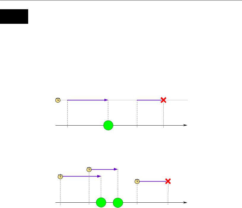
A timer is the simplest way to schedule some action in the model. Thus, timers are used to model delays and timeouts. Sometimes you do the same using timed transitions in statecharts, but timers might be more efficient. There are cases when desired behavior can be modeled only using timers. For example, a communication channel which is able to transmit an arbitrary number of messages concurrently can be modeled with the help of dynamic timers that are created for each message.
Static/Chart timers
5
active |
inactive |
active |
Time
restart(5) |
restart(10) |
reset() |
Action executed
Dynamic timers
3
5
Time
new |
new |
new |
reset() |
timer(5) |
timer(3) |
timer(7) |
timer deleted |
|
|
Actions |
|
|
|
executed, |
|
|
|
timers deleted |
|
Figure 110. Static and dynamic timers
218 |
© 1992-2004 XJ Technologies http://www.xjtek.com |

AnyLogic V User’s Manual
There are two types of timers: dynamic timers and static timers. The latter may be declared graphically, in which case a timer is called chart timer. The difference between the dynamic timer and the static timer is that the dynamic timer deletes itself upon expiry, whereas static timer survives and can be restarted. The timeout of a dynamic timer is passed to its constructor, whereas the timeout of a static timer is specified by calling the method restart() of the timer. A chart timer has even more features: you can specify that it expires either once or cyclically, or works in the manual mode like an ordinary static timer.
A timer has an action associated with it – code that is executed when the timer expires.
8.1 Dynamic timers
A dynamic timer is created using the operator new and the timeout is passed to the object’s constructor. Time counting begins at the moment of timer construction. When the timeout expires, AnyLogic calls the method action() of the timer and then deletes the timer. If the method reset() of the timer is called before expiry, the timer is deleted and its method action() is never called.
The easiest way to define a dynamic timer class is to use the Project window of AnyLogic. However, you can define a dynamic timer class anywhere in the code – e.g., in the Additional class code or in an external file. Then you would have to subclass from DynamicTimer and override the method action().
►To define a new dynamic timer class
1.Click the New Dynamic Timer Class  toolbar button, or Choose Insert|New Dynamic Timer Class… from the main menu. The New Dynamic Timer Class dialog box is displayed.
Specify the name of the new dynamic timer class, choose the active object class, which will contain the timer class, and click OK.
2.Alternatively, in the Project window, right-click the active object class, which will contain the timer class, and choose New Dynamic Timer Class… from the popup menu.
The New Dynamic Timer Class dialog box is displayed.
Specify the name of the new dynamic timer class and click OK.
© 1992-2004 XJ Technologies http://www.xjtek.com |
219 |

Chapter 8. Timers
A dynamic timer class has the following properties, specified on the General and Code pages of the Properties window correspondingly:
General properties
Name – name of the dynamic timer class.
Parameters – [optional] set of formal parameters of the class. Every parameter should be declared in form: Type Name Default, where Type is the type of the parameter, Name is the name of the parameter, Default is the optional default value of the parameter. When instantiating the class, actual parameters may be specified or default ones may be left. The parameters can be accessed as member variables of the timer object.
Exclude from build – if set, the dynamic timer class is excluded from the model.
Code properties
Constructor code – [optional] sequence of Java statements to be executed on dynamic timer construction.
Expiry action – [optional] sequence of Java statements to be executed on timer expiry.
Additional class code – [optional] Java code to be inserted into the class definition. Constants, variables, and methods can be defined here.
8.2 Static and chart timers
Unlike a dynamic timer, a static timer can expire any number of times. To start a static timer, you call its method restart(),specifying the timeout value as a parameter. When the timer expires, it calls the method action(). By calling the method reset(), you deactivate the timer until the next call to restart().
The easiest way to define a static timer is to place a chart timer on the structure diagram of an active object class. However, you can define a static timer class anywhere else in the model – e.g., in the Additional class code or in an external files. Then you would have to subclass from StaticTimer class and override the method action(). A chart timer adds more features to a static timer: you can specify that it expires either once or cyclically, or works in the manual mode like an ordinary static timer.
220 |
© 1992-2004 XJ Technologies http://www.xjtek.com |
AnyLogic V User’s Manual
►To declare a chart timer
1.Click the Chart Timer  toolbar button, or
Choose Draw|Structure|Chart Timer from the main menu.
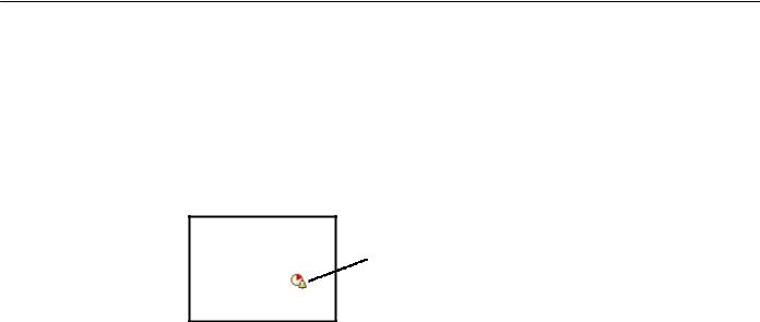
2.Click the place on the diagram where you want to place the chart timer. A chart timer appears, displayed as an icon, see Figure 111.
Chart timer
Figure 111. Chart timer
Chart timer defines a static timer within an active object. Chart timer is displayed as an icon and can be placed anywhere on the structure diagram – inside or outside this object.
Chart timer has the following properties:
Properties
Name – name of the chart timer.
No expiry/Expire once/Cyclic – determines whether the timer is in the manual mode, or expires once, or expires cyclically.
Expire at startup – applies to a cyclic timer only. If set, the timer first expires immediately at model startup. Otherwise it first expires after a timeout.
Timeout – expression that is evaluated to obtain the timeout. This can be a real number, call to a method, random expression, etc.
Expiry action – [optional] sequence of Java statements to be executed on expiry.
Exclude from build – if set, the chart timer is excluded from the model.
Show name – if set, the name of the chart timer is shown on the structure diagram.
© 1992-2004 XJ Technologies http://www.xjtek.com |
221 |

Chapter 9. Statecharts
9. Statecharts
During its lifetime an active object performs operations in response to external or internal events and conditions. Existence of a state within an active object means that the order in which operations are invoked is important. For some objects, this eventand time-ordering of operations is so pervasive that you can best characterize the behavior of such objects in terms of a state transition diagram – a statechart. A statechart is used to show the state space of a given algorithm, the events that cause a transition from one state to another, and the actions that result from state change.
By using statecharts you can visually capture a wide variety of discrete behaviors, much more rich than just idle/busy, open/closed, or up/down status offered by most block-based tools.
AnyLogic statecharts are UML compliant. They preserve graphical appearance, attributes, and execution semantics defined in UML.
AnyLogic supports hybrid statecharts – the most natural and powerful way to integrate discrete logic and continuous time behavior. In hybrid statecharts you can associate a set of differential and algebraic equations with a state on a statechart diagram. When a state transition is taken as a result of, e.g., some discrete event, the system of equations changes – this way, discrete logic affects the continuous time behavior. If you specify a condition over continuously changing variables as a trigger of a transition, you get the opposite effect: continuous time behavior impacts the discrete part of the system.
9.1 Creating a statechart
A statechart is declared on a structure diagram and implemented using a statechart diagram.
►To create a statechart
1.Click the Statechart  toolbar button, or
Choose Draw|Structure|Statechart from the main menu.
2.Click the place on the structure diagram where you want to place the statechart. A statechart appears, displayed as an icon, see Figure 112.
222 |
© 1992-2004 XJ Technologies http://www.xjtek.com |

AnyLogic V User’s Manual
Statechart
Figure 112. Statechart
Once the statechart is created, you can specify the statechart name in the text line editor opened on the right of the statechart in the structure diagram.
A statechart has the following set of properties:
Properties
Name – name of the statechart.
Deferred events – [optional] a set of signal event descriptors separated by commas, e.g.: new SignalEvent1(), new SignalEvent2(“param”). Deferred events for this statechart are events that match the given descriptors.
After initialize action – [optional] the code to be called when the statechart is about to run after it has been initialized.
Before step action – [optional] the code to be called each time before the statechart switches from one state to another.
After step action – [optional] the code to be called each time after the statechart switches from one state to another.
Node action – [optional] the code to be called each time before the statechart could execute an action associated with entering a state or a transition (including pseudo states, branch transitions, etc.), even if such action is not defined. Please note that the function may be called several times during a single step.
Exclude from build – if set, the statechart is excluded from the model.
Show name – if set, the name of the statechart is shown on the structure diagram.
© 1992-2004 XJ Technologies http://www.xjtek.com |
223 |
Chapter 9. Statecharts
9.2 Statechart diagram
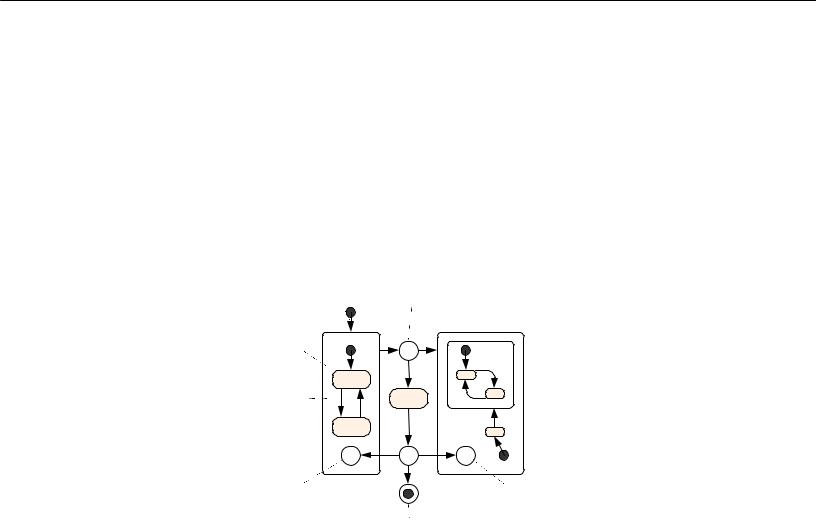
The behavior of a statechart is defined on a statechart diagram. AnyLogic supports the following statechart constructs: state (see section 9.2.1.1, “State”), transition (see section 9.2.1.2, “Transition”), initial state pointer (see section 9.2.1.3, “Initial state pointer”), final state (see section 9.2.1.5, “Final state”), branch (see section 9.2.1.6, “Branch”), shallow and deep history states (see section 9.2.1.7, “Shallow history and deep history states”), and text box (see section 9.2.1.8, “Text box”), see Figure 113. In this section all these constructs are described in detail.
Initial state pointer |
Branch |
Text box |
|
||
State |
B |
|
|
|
|
Transition |
|
|
H |
B |
H* |
Shallow |
|
Deep |
history state |
|
|
|
history state |
|
|
|
|
|
Final state |
|
Figure 113. Statechart diagram
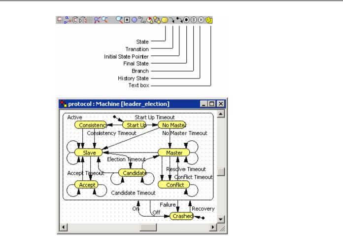
A statechart diagram is edited in the statechart editor using the statechart toolbar, see Figure 114.
224 |
© 1992-2004 XJ Technologies http://www.xjtek.com |
AnyLogic V User’s Manual
Figure 114. Statechart editor and toolbar
►To open the statechart diagram of a statechart
1.Double-click the statechart in the Project window, or Double-click the statechart on a structure diagram, or
Right-click the statechart on a structure diagram and choose Open Statechart from the popup menu.
►To open the structure diagram of the statechart owner object
1.Right-click the empty area of the statechart diagram and choose Up to Parent from the popup menu
Statechart editor shares a large set of generic editing operations described in section 1.5.2, “Diagram editors. Generic operations”.
© 1992-2004 XJ Technologies http://www.xjtek.com |
225 |

Chapter 9. Statecharts
9.2.1.1 State
A state represents a location of control with a particular set of reactions to conditions and/or events. A state can be either simple or, if it contains other states, composite. Control always resides in one of simple states, but the current set of reactions is a union of those of the current simple state and of all composite states containing it – i.e., a transition exiting any of these states may be taken.
Composite
state
Simple state
Simple state 


Figure 115. States
►To draw a state
1.Click the State  toolbar button, or
Choose Draw|Statechart|State from the main menu.
2.Click the place in the diagram where you want to put the state. Then drag to choose the size of the state.
A state has the following properties:
Properties
Name – name of the state.
Deferred events – [optional] set of signal event descriptors separated by commas, e.g.: new SignalEvent1(), new SignalEvent2(“param”). Deferred events for this state are events that match the given descriptors.
Equations – [optional] set of differential equations, algebraic equations, and formulas given in form described in Chapter 5, “Equations”. These equations are active while the statechart stays in the state.
226 |
© 1992-2004 XJ Technologies http://www.xjtek.com |