


Virtuoso AMS Environment User Guide
Elaborating, Simulating, and Plotting Results
The following table briefly describes the fields. For more information, see the“ncelab Command Syntax and Options” section in the “Elaborating” chapter of theVirtuoso
AMS Simulator User Guide.
Field |
Corresponding ncelab |
Effect |
|
Option |
|
|
|
|
Print informational |
-messages |
Prints informative messages during |
messages |
|
elaboration. |
Display runtime |
-status |
Prints statistics on memory and |
status |
|
CPU usage after elaboration. |
Suppress all |
-neverwarn |
Disables printing of all warning |
warnings |
|
messages. |
Suppress specific |
-nowarn |
Disables printing of the specified |
warnings |
|
warning message. |
Suppress output to |
-nostdout |
Suppresses the printing of most |
screen |
|
output to the screen. |
Suppress copyright |
-nocopyright |
Suppresses printing of the copyright |
information |
|
banner. |
Print messages |
-libverbose |
Displays messages about module |
about resolving |
|
and UDP instantiations. |
instances (Verilog |
|
|
only) |
|
|
Enable code |
-coverage |
Enables coverage instrumentation. |
coverage for entire |
|
|
design (digital only) |
|
|
|
|
|
4. When you are done changing options, click OK to save your changes.
Setting Simulator Options
AMS Designer provides many options for the simulator, that allow you to tailor the simulator behavior for your needs. You can access the option settings for the simulator from the
Cadence hierarchy editor.
1.From the hierarchy editor, choose AMS – Options.
If the AMS menu entry is not visible, follow the instructions in “Specifying the Behavior of the Netlister and Compilers” on page 74.
April 2004 |
247 |
Product Version 5.3 |
Virtuoso AMS Environment User Guide
Elaborating, Simulating, and Plotting Results
The AMS Options window appears.
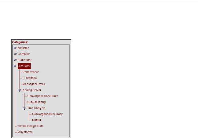
2.Expand the Simulator category as necessary to find the options you want to change.
When fully expanded, the Simulator category displays the following subcategories.
3.Highlight the category that you want to change.
The corresponding pane appears. For information about the fields in each pane, see the following cross-references:
For information about this category |
See |
|
Simulator |
“Specifying Basic Optionsorf the |
|
|
Simulator” on page 249 |
|
Performance |
“SpecifyingPerformance Options for the |
|
|
Simulator” on page 251 |
|
C Interface |
“Specifying C Interface Options for the |
|
|
Simulator” on page 255 |
|
Messages/Errors |
“Specifying Message and Error Options |
|
|
for the Simulator” on page 256 |
|
Analog Solver |
“Specifying General Options for the |
|
|
Analog Solver” on page 258 |
|
April 2004 |
248 |
Product Version 5.3 |

Virtuoso AMS Environment User Guide
Elaborating, Simulating, and Plotting Results
For information about this category |
See |
Convergence/Accuracy |
“Specifying Convergence and Accuracy |
|
Options for the Analog Solver” on |
|
page 260 |
Output/Debug |
“Specifying Output and Debug Options |
|
for the Analog Solver” on page 265 |
Tran Analysis |
“Specifying aransientT Analysis for the |
|
Analog Solver” on page 268 |
Convergence/Accuracy |
“Specifying Convergence and Accuracy |
|
Options for a Transient Analysis” on |
|
page 269 |
Output |
“Specifying Output and Debug Options |
|
for a Transient Analysis” on page 273 |
Specifying Basic Options for the Simulator |
|
To specify basic options for the simulator,. |
|
1.From the hierarchy editor, choose AMS – Options.
If the AMS menu entry is not visible, follow the instructions in “Specifying the Behavior of the Netlister and Compilers” on page 74.
The AMS Options window appears.
2.Highlight the Simulator category.
April 2004 |
249 |
Product Version 5.3 |
Virtuoso AMS Environment User Guide
Elaborating, Simulating, and Plotting Results
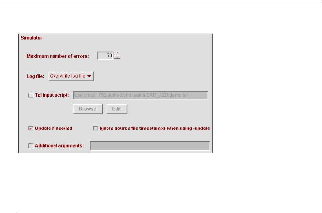
The Simulator pane opens.
3.Fill in the fields as necessary.
The following table briefly describes the fields and tells you where to go for more information. All of the cross-references in the table are to the “Simulating” chapter of the
Virtuoso AMS Simulator User Guide.
Field |
Corresponding ncsim |
Effect |
|
Option |
|||
|
|
||
|
|
|
|
Maximum number of |
-errormax |
Specifies the maximum number of |
|
errors |
|
errors to process. Errors caused by |
|
|
|
Tcl command files or by interactive |
|
|
|
Tcl commands do not count toward |
|
|
|
the limit. |
|
Log file |
-append_log, |
Determines whether a log file is to |
|
|
-nolog |
be created, and, if so, whether the |
|
|
|
new information is to overwrite any |
|
|
|
existing log or be appended. |
|
Tcl input script |
-input |
Specifies a script file to run at the |
|
|
|
beginning of the simulation. |
|
Update if needed |
-update |
Recompiles out-of-date design units |
|
|
|
as necessary. |
|
Ignore source file |
-nosource |
Turns off source file timestamp |
|
timestamps when |
|
checking when using the -update |
|
using -update |
|
option. |
April 2004 |
250 |
Product Version 5.3 |
Virtuoso AMS Environment User Guide
Elaborating, Simulating, and Plotting Results
Field |
Corresponding ncsim |
Effect |
|
Option |
|||
|
|
||
|
|
|
|
Additional |
|
To pass to the simulator arguments |
|
arguments |
|
that are not available in the GUI, |
|
|
|
type the arguments into this field. |
|
|
|
|
4. Click OK to save your changes.
Specifying Performance Options for the Simulator
To specify performance options for the simulator,
1. From the Cadence hierarchy editor, choose AMS – Options.
April 2004 |
251 |
Product Version 5.3 |
Virtuoso AMS Environment User Guide
Elaborating, Simulating, and Plotting Results
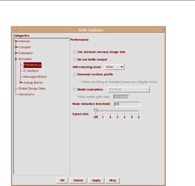
2.In the AMS Options window, choose Simulator – Performance to open the AMS
Options window to the Performance pane.
3.Select fields as necessary.
The following table briefly describes the fields and tells you the corresponding option or option card. For additional information about ncsim options, see the “ncsimCommand Syntax and Options” section, in the “Simulating” chapter of theVirtuoso AMS
Simulator User Guide. For additional information about the mos_method options card,
April 2004 |
252 |
Product Version 5.3 |

Virtuoso AMS Environment User Guide
Elaborating, Simulating, and Plotting Results
see the “Immediate Set Options (options)” section, in the “Specifying Controls for the
Analog Solver” chapter of the Virtuoso AMS Simulator User Guide.
Field |
Corresponding Option |
Effect |
|
|
|
Use reduced |
ncsim -redmem |
Turns off loading of intermediate |
memory image size |
|
objects generated by the compiler. |
Do not buffer output |
ncsim -unbuffered |
Bypasses the file I/O buffer so that |
|
|
data displays immediately. |
OMI checking level |
ncsim |
Specifies the OMI checking level to |
|
-omicheckinglevel |
use. |
Generate runtime |
ncsim -profile |
Generates a run time profile of the |
profile |
|
design. The profiling information is |
|
|
written to the ncprof.out file only |
|
|
after the simulator session is exited. |
|
|
Depending on the simulator you are |
|
|
using, this command might be |
|
|
restricted to digital only. |
Allow profiling of |
ncsim -profthread |
Allows threaded processes to be |
threaded processes |
|
profiled. |
(digital only) |
|
|
April 2004 |
253 |
Product Version 5.3 |

Virtuoso AMS Environment User Guide
Elaborating, Simulating, and Plotting Results
Field |
Corresponding Option |
Effect |
|
|
|
Model evaluation |
|
When checked, writes the selected |
|
|
mos_method option, as described |
|
|
for Standard or Accelerated |
|
|
(table model). When unchecked, |
|
|
writes nothing. |
|
|
This field is disabled when theUse |
|
|
simulation control file field, in the |
|
|
Analog Solver pane, is turned on. |
|
|
(This field appears only if the AMS |
|
|
simulator you are running supports |
|
|
it.) |
Standard |
The analog simulation |
Instructs the simulator not to use |
|
control (.scs) file option table models for any instances. |
|
|
card: |
|
|
amsOptions options |
|
|
+ mos_method = s |
|
Accelerated |
The analog simulation |
Instructs the simulator to use table |
(table model) |
control (.scs) file card: |
models whenever possible. This |
|
amsOptions options |
global option applies to the entire |
|
+ mos_method = a |
simulated design. You can override |
|
|
this instruction on specific model |
|
|
cards by setting mos_method = s |
|
|
as an option on those cards. |
Table model grid |
The analog simulation |
Specifies the voltage increment for |
size |
control (.scs) file option the mosfet table model interpolation |
|
|
card: |
grid. For more information, see |
|
amsOptions options |
“scmosvres” on page 506. |
|
+ mos_vres = value |
|
Node reduction |
The analog simulation |
Specifies the threshold below which |
threshold |
control (.scs) file option parasitic node reduction occurs. |
|
card:
amsOptions options + maxrsd = value
April 2004 |
254 |
Product Version 5.3 |
Virtuoso AMS Environment User Guide
Elaborating, Simulating, and Plotting Results
Field |
Corresponding Option |
Effect |
|
|
|
Speed dial |
The analog simulation |
Establishes the tradeoff between |
|
control (.scs) file option simulation performance and |
|
|
card: |
accuracy. |
amsOptions options
+speed = value
4.When you are done changing options, click OK to save your changes.
Specifying C Interface Options for the Simulator
To specify C interface options for the simulator,
1.From the Cadence hierarchy editor, choose AMS – Options.
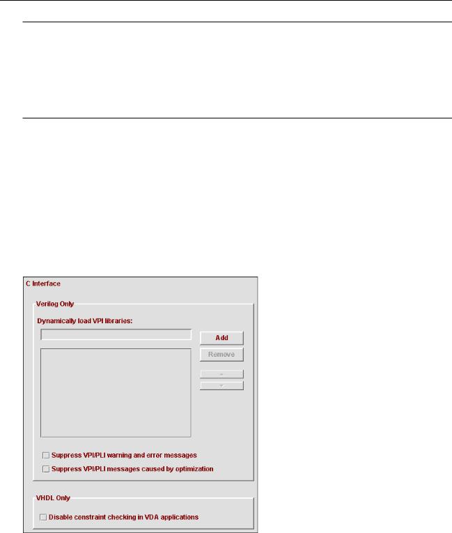
2.In the AMS Options window, choose Simulator – C Interface to open the AMS Options window to the C Interface pane.
3. Fill in and select fields as necessary.
April 2004 |
255 |
Product Version 5.3 |

Virtuoso AMS Environment User Guide
Elaborating, Simulating, and Plotting Results
The following table briefly describes the fields. For additional information, see the“ncsim Command Syntax and Options” section, in the “Simulating” chapter of theVirtuoso
AMS Simulator User Guide.
Field |
Corresponding ncsim |
Effect |
|
Option |
|||
|
|
||
|
|
|
|
Verilog Only |
|
|
|
Dynamically load |
-loadvpi |
Dynamically loads a VPI |
|
VPI libraries |
|
application. |
|
Suppress VPI/PLI |
-plinowarn |
Disables printing of PLI warning |
|
warning and error |
|
and error messages. |
|
messages |
|
|
|
Suppress VPI/PLI |
-plinooptwarn |
Prints a warning message only the |
|
messages |
|
first time that a PLI read, write, or |
|
caused by |
|
connectivity access violation is |
|
optimization |
|
detected. |
|
VHDL Only |
|
|
|
Disable |
-nocifcheck |
Disables constraint checking in |
|
constraint |
|
VHDL Design Access (VDA) |
|
checking in VDA |
|
functions, for increased |
|
applications |
|
performance. |
|
|
|
|
4. When you are done changing options, click OK to save your changes.
Specifying Message and Error Options for the Simulator
To specify message and error options for the simulator,
1. From the Cadence hierarchy editor, choose AMS – Options.
April 2004 |
256 |
Product Version 5.3 |
Virtuoso AMS Environment User Guide
Elaborating, Simulating, and Plotting Results
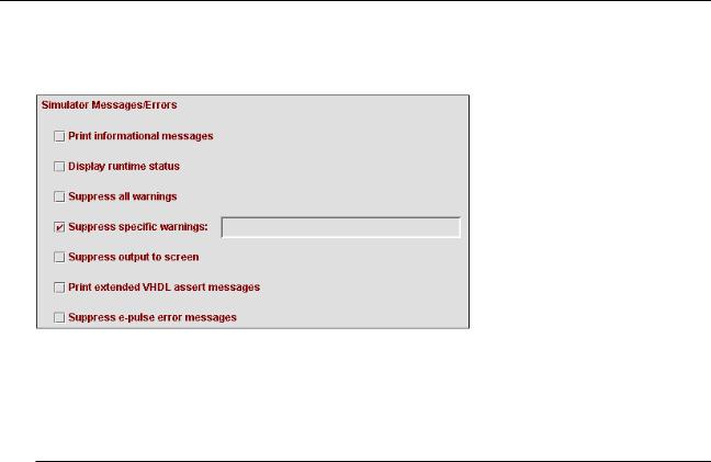
2.In the AMS Options window, choose Simulator – Messages/Errors to open the AMS
Options window to the Simulator Messages/Errors pane.
3.Fill in and select fields as necessary.
The following table briefly describes the fields and tells you where to go for more information. For additional information, see the “ncsim Command Syntax and Options” section, in the “Simulating” chapter of theVirtuoso AMS Simulator User Guide.
Field |
Corresponding ncsim |
Effect |
|
Option |
|||
|
|
||
|
|
|
|
Print informational |
-messages |
Prints informative messages during |
|
messages |
|
simulation. |
|
Display runtime |
-status |
Prints statistics on memory and |
|
status |
|
CPU usage after simulation. |
|
Suppress all |
-neverwarn |
Disables printing of all warning |
|
warnings |
|
messages. |
|
Suppress specific |
-nowarn |
Disables printing of the specified |
|
warnings |
|
warning message. |
|
Suppress output to |
-nostdout |
Suppresses the printing of most |
|
screen |
|
output to the screen. |
|
Print extended |
-extassertmsg |
Prints extended assert message |
|
VHDL assert |
|
Information. |
|
messages |
|
|
|
Suppress e-pulse |
-epulse_no_msg |
Suppresses e-pulse error |
|
error messages |
|
messages. |
|
|
|
|
April 2004 |
257 |
Product Version 5.3 |
Virtuoso AMS Environment User Guide
Elaborating, Simulating, and Plotting Results
4. When you are done changing options, click OK to save your changes.
Specifying General Options for the Analog Solver
In the analog solver panes, you can specify many options that determine how the analog simulation proceeds.
When Analog Solver Options Are Written to the Analog Control File
If you specify, for an analog solver option, a value that is not the simulator default, AMS
Designer writes the option and value to the analog control file, which controls the simulation.
However, when a value in the analog solver panes is the same as the corresponding simulator default value, AMS Designer does not write the option to the analog control file. In this situation, the simulator uses the corresponding value set in the model files, if there is such a value. If there is no corresponding value in the model files, the simulator uses the simulator default value. For more information about how the AMS simulator determines what value to use for options, see the “Immediate Set Options (options)” section in Chapter 8, of the Virtuoso AMS Simulator User Guide.
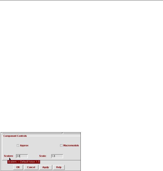
Popping Up Information About Analog Solver Options
Holding the cursor over a label in the analog solver panes pops up information about the default value for that option. For example, in the following screen capture, the pop-up contains information about the default value of the option.
Specifying Basic Information for the Analog Solver
To specify basic information for the analog solver,
1. From the Cadence hierarchy editor, choose AMS – Options.
April 2004 |
258 |
Product Version 5.3 |
Virtuoso AMS Environment User Guide
Elaborating, Simulating, and Plotting Results
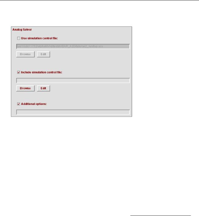
2.In the AMS Options window, choose Simulator – Analog Solver to display the Analog
Solver pane.
3.Choose how the analog solver is to be controlled.
If you want the analog solver to use an existing simulation control file,
a.Check the box next to Use simulation control file.
b.Specify the control file in theUse simulation control file field. The path can contain shell environment variables.
You can type the fully qualified path and name, or clickBrowse to locate the file that you want to use. (If you do not have an existing file, you can open a template by typing a name and clicking Edit.)
You can also type in a relative path, which is evaluated relative to the run directory, or a simple file name to refer to a file that is located in the run directory.
The simulation control file contains commands that tell the analog solver how to simulate the design. For more information, see the “Specifying Controlsorf the Analog Solver” chapter, in the Virtuoso AMS Simulator User Guide.
If you want to use the AMS Options GUI to generate a new simulation control file,
a.Ensure that the box next to Use simulation control file is not checked.
b.Use the Convergence/Accuracy, Output/Debug, and Tran Analysis subcategories of the Analog Solver category to specify the behavior of the simulator.
April 2004 |
259 |
Product Version 5.3 |

Virtuoso AMS Environment User Guide
Elaborating, Simulating, and Plotting Results
If you use this approach, you must specify a stop time, at least. For guidance, see “Specifying aransientT Analysis for the Analog Solver” on page 268.
4.(Optional) Type the name of a simulation control file into theInclude simulation control file field.
The path can contain shell environment variables.
The specified simulation control file is included in the simulation control file generated from the options you specify in the GUI. For example, you type
~/fpga.scs
into the Include simulation control file field. When you clickOK, AMS Designer checks that the file exists, and if it does, includes it in the generated simulation control
file with a statement like this.
include "/usr1/mnt4/lorenp/fpga.scs"
5.(Optional) Type into the Additional options field any options that you want to append to the end of the options card in the simulation control file.
For example, you type
rawfile = "/hm/kat/amsAnalysis"
into the Additional options field. AMS Designer adds the value to the end of the options card, like this.
amsOptions options
+gmin_check = all
+inventory = detailed
+rawfile = "/hm/kat/amsAnalysis"
6.When you finish setting options, clickOK to save your changes.
Specifying Convergence and Accuracy Options for the Analog Solver
You can access the convergence and accuracy option settings for the analog solver from the
Cadence hierarchy editor.
April 2004 |
260 |
Product Version 5.3 |
Virtuoso AMS Environment User Guide
Elaborating, Simulating, and Plotting Results
1.In the AMS Options window, choose Simulator – Analog Solver – Convergence/
Accuracy to open the AMS Options window to the Convergence/Accuracy pane.
2.Fill in and select fields as necessary.
The following table briefly describes the fields and tells you where to go for more information. For additional information, see the “Immediate Set Options (options)” section, in the “Specifying Controls for the Analog Solver” chapter of theVirtuoso AMS
April 2004 |
261 |
Product Version 5.3 |

Virtuoso AMS Environment User Guide
Elaborating, Simulating, and Plotting Results
Simulator User Guide and the “Immediate Set Options (options)” section, in the “AnalysisStatements” chapter of the Virtuoso Spectre Circuit Simulator Reference.
|
Corresponding |
|
Field |
spectre Option and |
Effect |
|
Parameter |
|
|
|
|
Tolerances |
|
|
Reltol |
options reltol |
Specifies the maximum relative |
|
|
tolerance for values computed in |
|
|
the last two iterations of a solution. |
Vabstol |
options vabstol |
Specifies the absolute tolerance for |
|
|
differences in the computed values |
|
|
of the voltages in the last two |
|
|
iterations of a solution. |
Iabstol |
options iabstol |
Specifies the absolute tolerance for |
|
|
differences in the computed values |
|
|
of the currents in the last two |
|
|
iterations of a solution. |
April 2004 |
262 |
Product Version 5.3 |

Virtuoso AMS Environment User Guide
Elaborating, Simulating, and Plotting Results
|
Corresponding |
|
|
|
Field |
spectre Option and |
Effect |
||
|
Parameter |
|
|
|
|
|
|
|
|
Temperature |
|
|
|
|
Temp |
options temp |
Specifies the circuit temperature in |
||
|
|
degrees Celsius. |
||
Tnom |
options tnom |
Specifies the measurement |
||
|
|
(nominal) temperature in degrees |
||
|
|
Celsius. |
||
Tempeffects |
options |
Defines how temperature affects |
||
|
tempeffects |
the built-in primitive components. It |
||
|
|
takes the following three values: |
||
|
|
vt–Only thermal voltage |
||
|
|
V |
|
kT |
|
|
t |
= ------ |
|
|
|
|
q |
|
|
|
can vary with temperature. |
||
|
|
tc–In addition to thermal voltage, |
||
|
|
the component temperature |
||
|
|
coefficient parameters (parameters |
||
|
|
that start with tc, such as tc1, and |
||
|
|
tc2) are active. Use this setting |
||
|
|
when you want to disable the |
||
|
|
temperature effects for nonlinear |
||
|
|
devices. |
||
|
|
all–All built-in temperature models |
||
|
|
are enabled. |
||
Convergence |
|
|
|
|
Homotopy |
options homotopy |
Specifies the method to use if |
||
|
|
convergence fails on the initial DC |
||
|
|
analysis attempt. |
||
Limit |
options limit |
Specifies the limiting algorithm used |
||
|
|
to aid DC convergence. |
||
April 2004 |
263 |
Product Version 5.3 |

Virtuoso AMS Environment User Guide
Elaborating, Simulating, and Plotting Results
|
Corresponding |
|
Field |
spectre Option and |
Effect |
|
Parameter |
|
|
|
|
Resistance |
|
|
Gmin |
options gmin |
Specifies the minimum |
|
|
conductance across each nonlinear |
|
|
device. |
Gmin check |
options gmin_check |
Specifies how the effect ofGmin (if |
|
|
that effect is significant) is to be |
|
|
reported. |
Rforce |
options rforce |
Specifies the resistance to be used |
|
|
when forcing nodesets and node- |
|
|
based initial conditions. |
Matrix |
|
|
Pivrel |
options pivrel |
Specifies the relative pivot |
|
|
threshold. |
Pivabs |
options pivabs |
Specifies the absolute pivot |
|
|
threshold. |
Pivotdc |
options pivotdc |
Specifies that numeric pivoting be |
|
|
used on every iteration of DC |
|
|
analysis. |
April 2004 |
264 |
Product Version 5.3 |

Virtuoso AMS Environment User Guide
Elaborating, Simulating, and Plotting Results
|
Corresponding |
|
Field |
spectre Option and |
Effect |
|
Parameter |
|
|
|
|
Component Controls |
|
|
Approx |
options approx |
Specifies that approximate models |
|
|
are to be used. The difference |
|
|
between approximate and exact |
|
|
models is generally very small. |
Macromodels |
options |
Specifies that the circuit contains |
|
macromodels |
macromodels. Sometimes |
|
|
specifying this information improves |
|
|
performance. |
Scalem |
options scalem |
Specifies the scaling factor for |
|
|
models. |
Scale |
options scale |
Specifies the scaling factor for |
|
|
device instances. |
Compatible |
options compatible |
Specifies a simulator. AMS |
|
|
Designer changes device models to |
|
|
improve consistency with the |
|
|
models in the specified simulator. |
|
|
|
3. When you are done changing options, click OK to save your changes.
Specifying Output and Debug Options for the Analog Solver
You can access the output and debug option settings for the analog solver from the Cadence hierarchy editor.
April 2004 |
265 |
Product Version 5.3 |
Virtuoso AMS Environment User Guide
Elaborating, Simulating, and Plotting Results
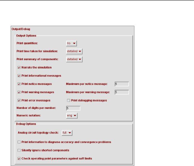
1.In the AMS Options window, choose Simulator – Analog Solver – Output/Debug to open the AMS Options window to the Output/Debug pane.
2.Fill in and select fields as necessary.
The following table briefly describes the fields. For additional information, see the “Immediate Set Options (options)” section, in the “Specifying Controls for the Analog
Solver” chapter of the Virtuoso AMS Simulator User Guide and the “Immediate Set
April 2004 |
266 |
Product Version 5.3 |

Virtuoso AMS Environment User Guide
Elaborating, Simulating, and Plotting Results
Options (options)” section, in the “Analysis Statements” chapter of theVirtuoso
Spectre Circuit Simulator Reference.
|
Corresponding |
|
Field |
spectre Option and |
Effect |
|
Parameter |
|
|
|
|
Output Options |
|
|
Print quantities |
options quantities |
Prints quantities. |
Print time taken |
options audit |
Prints the time required by various |
for simulation |
|
parts of the simulation. |
Print summary of |
options inventory |
Prints a summary of the |
components |
|
components used. |
Narrate the |
options narrate |
Narrates the simulation. |
simulation |
|
|
options info |
Prints informational messages. |
|
informational |
|
|
messages |
|
|
Print notice |
options note |
Prints notice messages. |
messages |
|
|
Maximum per |
options maxnotes |
Specifies the maximum number of |
notice message |
|
times any particular notice will be |
|
|
issued per analysis. |
Print warning |
options warn |
Prints warning messages. |
messages |
|
|
Maximum per |
options maxwarn |
Specifies the maximum number of |
warning message |
|
times any particular warning will be |
|
|
issued per analysis. |
Print error |
options error |
Prints error messages. |
messages |
|
|
Print debugging |
options debug |
Prints debugging information. |
messages |
|
|
Number of digits |
options digits |
Specifies the number of digits used |
per number |
|
when printing numbers. |
Numeric notation |
options notation |
Specifies the notation to be used |
|
|
when displaying real numbers. |
April 2004 |
267 |
Product Version 5.3 |
Virtuoso AMS Environment User Guide
Elaborating, Simulating, and Plotting Results
|
Corresponding |
|
Field |
spectre Option and |
Effect |
|
Parameter |
|
|
|
|
Debug Options |
|
|
Analog circuit |
options topcheck |
Checks the circuit topology for |
topology check |
|
errors. |
Print information |
options diagnose |
Prints information that might help |
to diagnose |
|
diagnose accuracy and |
accuracy and |
|
convergence problems. |
convergence |
|
|
problems |
|
|
Silently ignore |
options ignshorts |
Tells the simulator to ignore shorted |
shorted |
|
components silently. |
components |
|
|
Check operating |
options opptcheck |
Checks the operating point |
point parameters |
|
parameters against soft limits. |
against soft limits |
|
|
|
|
|
3. When you are done changing options, click OK to save your changes.
Specifying a Transient Analysis for the Analog Solver
You can access the transient analysis option settings for the analog solver from the Cadence hierarchy editor.
1.In the AMS Options window, choose Simulator – Analog Solver – Tran Analysis to open the AMS Options window to the Tran Analysis pane.
April 2004 |
268 |
Product Version 5.3 |

Virtuoso AMS Environment User Guide
Elaborating, Simulating, and Plotting Results
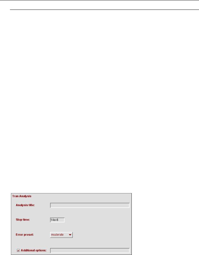
2.Fill in and select fields as necessary.
The following table briefly describes the fields. For additional information, see the
“Transient Analysis (tran)” section, in the “Specifying Controls for the Analog Solver” chapter of the Virtuoso AMS Simulator User Guide and the “Transient Analysis (tran)” section, in the “Analysis Statements” chapter of theVirtuoso Spectre Circuit
Simulator Reference.
|
Corresponding |
|
Field |
spectre Option and |
Effect |
|
Parameter |
|
|
|
|
Analysis title |
tran title |
Specifies a title for the analysis. |
Stop time |
tran stop |
Specifies the stop time for the |
|
|
analysis. You must specify a value |
|
|
for this field. |
Error preset |
tran errpreset |
Specifies a collection of parameter |
|
|
settings for the analysis. |
Additional options |
|
Specifies additional options that you |
|
|
want to append to the end of the |
|
|
tran card in the simulation control |
|
|
file. |
|
|
For example, you type |
|
|
outputstart=0.0005 |
|
|
into the Additional options field. |
|
|
AMS Designer adds the value to the |
|
|
end of the tran card, like this. |
|
|
amsAnalysis tran |
|
|
+ stop = 0.001 |
|
|
+ method = euler |
|
|
+ relref = pointlocal |
|
|
+ outputstart=0.0005 |
|
|
|
3. When you are done changing options, click OK to save your changes.
Specifying Convergence and Accuracy Options for a Transient Analysis
You can access the convergence and accuracy option settings for the transient analysis from the Cadence hierarchy editor.
April 2004 |
269 |
Product Version 5.3 |
Virtuoso AMS Environment User Guide
Elaborating, Simulating, and Plotting Results
1.In the AMS Options window, choose Simulator – Analog Solver – Tran Analysis –
Convergence/Accuracy to display the Tran Convergence/Accuracy pane.
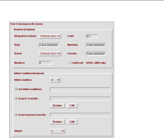
2.Fill in and select fields as necessary.
The following table briefly describes the fields. For additional information, see the
“Transient Analysis (tran)” section, in the “Specifying Controls for the Analog Solver” chapter of the Virtuoso AMS Simulator User Guide and the “Transient Analysis (tran)”
April 2004 |
270 |
Product Version 5.3 |
Virtuoso AMS Environment User Guide
Elaborating, Simulating, and Plotting Results
section, in the “Analysis Statements” chapter of theVirtuoso Spectre Circuit
Simulator Reference
|
Corresponding |
|
Field |
spectre Option and |
Effect |
|
Parameter |
|
|
|
|
Numerical Options |
|
|
Integration |
tran method |
Specifies the integration method to |
method |
|
use. |
Cmin |
tran cmin |
Specifies the minimum capacitance |
|
|
from each node to ground. |
Step |
tran step |
Specifies the minimum time step to |
|
|
use. You might need to set this |
|
|
value to maintain the aesthetics of |
|
|
computed waveforms. |
Maxstep |
tran maxstep |
Specifies the maximum time step. |
Relref |
tran relref |
Specifies the reference to use for |
|
|
the relative convergence criteria. |
Lteratio |
tran lteratio |
Specifies the ratio to use to |
|
|
compute LTE tolerances from |
|
|
Newton tolerance. |
Maxiters |
tran maxiters |
Specifies the maximum number of |
|
|
iterations per time step. |
Fastbreak |
tran fastbreak |
Specifies the evaluation method to |
(VHDL-AMS only) |
|
use for VHDL-AMS break |
|
|
statements. |
April 2004 |
271 |
Product Version 5.3 |

Virtuoso AMS Environment User Guide
Elaborating, Simulating, and Plotting Results
|
Corresponding |
|
Field |
spectre Option and |
Effect |
|
Parameter |
|
|
|
|
Initial Conditions/ |
|
|
Nodesets |
|
|
Initial conditions |
tran ic |
Specifies the objects for which the |
|
|
simulator is to set initial conditions. |
|
|
For example, you specify the value |
|
|
dev for this field. As a result, the |
|
|
generated simulation control file |
|
|
contains the ic = dev option. |
|
|
amsAnalysis tran |
|
|
+ stop = 0.001 |
|
|
+ ic = dev |
|
|
+ method = euler |
Set initial |
ic |
Specifies initial conditions for nodes |
conditions |
|
and devices in the design. |
|
|
For example, you type the following |
|
|
into this field. |
|
|
7=0 out=1 OpAmp1.comp=5 |
|
|
L1:1=1.0u |
|
|
As a result, the generated |
|
|
simulation control file contains the |
|
|
statement: |
|
|
ic 7=0 out=1 OpAmp1.comp=5 |
|
|
L1:1=1.0u |
Read IC from file |
tran readic |
Specifies a file that contains initial |
|
|
conditions. |
Read nodesets |
tran readns |
Specifies a file that contains |
from file |
|
nodesets. |
Skipdc |
tran skipdc |
If yes, there is no DC analysis for |
|
|
transient. |
|
|
|
3. When you are done changing options, click OK to save your changes.
April 2004 |
272 |
Product Version 5.3 |
Virtuoso AMS Environment User Guide
Elaborating, Simulating, and Plotting Results
Specifying Output and Debug Options for a Transient Analysis
You can access the output and debug option settings for the transient analysis from the
Cadence hierarchy editor.
1.In the AMS Options window, choose Simulator – Analog Solver – Tran Analysis –
Output to display the Tran Output pane.
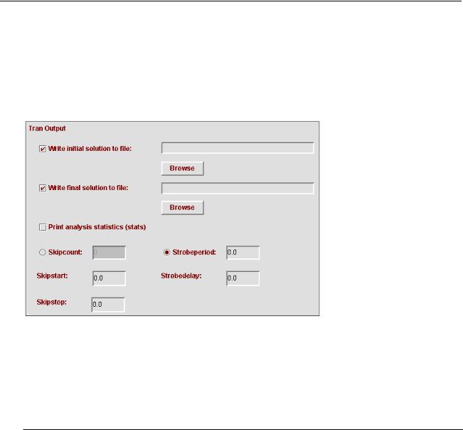
2.Fill in and select fields as necessary.
The following table briefly describes the fields. For additional information, see the
“Transient Analysis (tran)” section, in the “Specifying Controls for the Analog Solver” chapter of the Virtuoso AMS Simulator User Guide and the “Transient Analysis (tran)” section, in the “Analysis Statements” chapter of theVirtuoso Spectre Circuit Simulator Reference
|
Corresponding |
|
Field |
spectre Option and |
Effect |
|
Parameter |
|
|
|
|
Write initial solution |
tran write |
Directs the simulator to write the |
to file |
|
initial transient solution to the |
|
|
specified file. |
Write final solution to |
tran writefinal |
Directs the simulator to write the |
file |
|
final transient solution to the |
|
|
specified file. |
April 2004 |
273 |
Product Version 5.3 |