- •Contents
- •Preface
- •Related Documents
- •Typographic and Syntax Conventions
- •Creating HDL Modules for CDBA Cellviews
- •Creating HDL Data as You Save CDBA Cellviews
- •Creating HDL Data from Pre-existing CDBA Cellviews
- •Quick-Start Tutorial
- •The Circuit
- •AMS Designer Tools
- •Setting Up the Tutorial
- •Running from a Script
- •Running within the AMS Environment
- •Opening the Command Interpreter Window
- •Netlisting and Compiling
- •Elaborating and Simulating the Design
- •Summary
- •Setting Up the AMS Environment
- •Overview
- •The hdl.var File
- •The ams.env Files
- •AMS Designer Supports Design Management
- •Specifying the Text Editor to Use
- •Specifying Fonts for the Cadence Hierarchy Editor
- •Preparing to Use AMS Designer from the Hierarchy Editor
- •Netlisting
- •Netlisting Modes Supported by the AMS Netlister
- •Automatic Netlisting of a Cellview
- •Netlist Updating and Netlisting of Entire Designs
- •Netlisting from the UNIX Command Line
- •Library Netlisting
- •Netlisting of Cells in Response to Changes in CDF
- •Preparing Existing Analog Primitive Libraries for Netlisting
- •Specifying the Behavior of the Netlister and Compilers
- •Opening the AMS Options Windows
- •Setting Netlister Options from the Hierarchy Editor
- •Opening the CIW AMS Options Window
- •Setting Compiler Options
- •Viewing the AMS Netlister Log
- •Understanding the Output from the AMS Netlister
- •How Inherited Connections Are Netlisted
- •Inherited Signal Connections
- •Inherited Terminal Connections
- •Instance Values for Inherited Connections
- •Third-Party Tools and Other Cadence Tools
- •How Aliased Signals Are Netlisted
- •How m-factors (Multiplicity Factors) Are Netlisted
- •How Iterated Instances Are Netlisted
- •Passing Model Names as Parameters
- •Effect of the modelname, model, and modelName Parameters
- •Handling of the model* and componentName Parameters
- •Precedence of the model* and componentName Parameters
- •Specifying Parameters to be Excluded from Netlisting
- •Ignoring Parameters for Entire Libraries
- •Example: Specifying Parameters to Ignore
- •Ensuring that Floating Point Parameters Netlist Correctly
- •Working with Schematic Designs
- •Setting Schematic Rules Checker Options for AMS Designer
- •Creating Cellviews Using the AMS Environment
- •Preparing a Library
- •Creating the Symbol View
- •Using Blocks
- •Descend Edit
- •Inherited Connections
- •Global Signals in the Schematic Editor
- •Inherited Connections in a Hierarchy
- •How Net Expressions Evaluate
- •Net and Pin Properties
- •groundSensitivity and supplySensitivity Properties
- •Making Connect Modules Sensitive to Inherited Connection Values
- •Using External Text Designs
- •Overview of Steps for Using External Text Designs
- •Bringing Modules into a Cadence Library
- •Specifying the Working Library
- •Compiling into Libraries
- •Compiling into Temporary Libraries
- •Listing Compiled Modules
- •Using Text Blocks in Schematics
- •Using Modules Located in a Cadence Library
- •Preparing for Simulation
- •Using Analog Primitives
- •Using SPICE and Spectre Netlists and Subcircuits
- •Preparing to Use SPICE and Spectre Netlists and Subcircuits
- •Placing SPICE and Spectre Netlists and Subcircuits in a Schematic
- •Using Test Fixtures
- •Creating and Using a Textual Test Fixture
- •Creating a Textual Test Fixture
- •Using a Test Fixture
- •Example: Creating and Using a Test Fixture
- •Using Design Configurations
- •Ensuring HDL Design Unit Information Is Current
- •Preparing a Design for Simulation
- •Overview of AMS Design Prep
- •What AMS Design Prep Does to Prepare a Design for Simulation
- •When to Use AMS Design Prep
- •Specifying the Behavior of AMS Design Prep
- •Setting Options for Global Design Data
- •Specifying Global Signals
- •Specifying Design Variables
- •Specifying Model Files to Use During Elaboration
- •Running AMS Design Prep
- •The cds_globals Module
- •Global Signals
- •Design Variables
- •Setting Elaborator Options
- •Setting Simulator Options
- •Setting Waveform Selection Options
- •Creating Probes
- •Selecting Instances from the Virtuoso Schematic Editing Window
- •Selecting Buses
- •Selecting Instances from the Scope Navigator
- •Copying and Pasting Within Tables
- •Elaborating and Simulating
- •Viewing Messages
- •Plotting Waveforms After Simulation Ends
- •Starting the SimVision Waveform Viewer
- •Plotting Waveforms Selected on a Schematic (Direct Plot)
- •Using the amsdesigner Command
- •Examples
- •Producing Customized Netlists
- •Identifying the Sections of a Netlist
- •Using ams.env Variables to Customize Netlists
- •Using Netlisting Procedures to Customize Netlists
- •Examples: Problems Addressed by Customized Netlists
- •Example: Adjusting Parameter Values to Account for Number of Fingers
- •Example: Using Symbols that Represent Verilog Test Code
- •Data Objects Supported for Netlisting
- •Netlister Object
- •Formatter Object
- •Cellview Object
- •Parameter Object
- •Instance Object
- •SKILL Functions Supported for Netlisting
- •Default Netlisting Procedures
- •Netlisting Helper Functions
- •Variables for ams.env Files
- •How AMS Designer Determines the Set of Variables
- •Why AMS Designer Uses ams.env Files, Not .cdsenv Files
- •List of ams.env Variables
- •Detailed Descriptions of ams.env Variables
- •aliasInstFormat
- •allowDeviantBuses
- •allowNameCollisions
- •allowSparseBuses
- •allowUndefParams
- •amsCompMode
- •amsDefinitionViews
- •amsEligibleViewTypes
- •amsExcludeParams
- •amsExpScalingFactor
- •amsLSB_MSB
- •amsMaxErrors
- •amsScalarInstances
- •amsVerbose
- •analogControlFile
- •bindCdsAliasLib
- •bindCdsAliasView
- •cdsGlobalsLib
- •cdsGlobalsView
- •checkAndNetlist
- •checkOnly
- •checktasks
- •compileAsAMS
- •compileExcludeLibs
- •compileMode
- •connectRulesCell
- •connectRulesCell2
- •connectRulesLib
- •connectRulesView
- •detailedDisciplineRes
- •discipline
- •excludeViewNames
- •hdlVarFile
- •headerText
- •ieee1364
- •ifdefLanguageExtensions
- •incdir
- •includeFiles
- •includeInstCdfParams
- •initFile
- •instClashFormat
- •iterInstExpFormat
- •language
- •lexpragma
- •logFileAction
- •logFileName
- •macro
- •maxErrors
- •messages
- •modifyParamScope
- •ncelabAccess
- •ncelabAnnoSimtime
- •ncelabArguments
- •ncelabCoverage
- •ncelabDelayMode
- •ncelabDelayType through ncelabMessages
- •ncelabMixEsc
- •ncelabModelFilePaths
- •ncelabNeverwarn through ncelabVipdelay
- •ncsimArguments
- •ncsimEpulseNoMsg through ncsimExtassertmsg
- •ncsimGUI
- •ncsimLoadvpi through ncsimStatus
- •ncsimTcl
- •ncsimUnbuffered through ncsimUseAddArgs
- •ncvhdlArguments
- •ncvlogArguments
- •ncvlogUseAddArgs
- •netClashFormat
- •netlistAfterCdfChange
- •netlistMode
- •netlistUDFAsMacro
- •neverwarn
- •noline
- •nomempack
- •nopragmawarn
- •nostdout
- •nowarn
- •paramDefVals
- •paramGlobalDefVal
- •pragma
- •processViewNames
- •prohibitCompile
- •runNcelab
- •runNcsim
- •scaddlglblopts
- •scaddltranopts
- •scale
- •scalem
- •scannotate
- •scapprox
- •scaudit
- •sccheckstmt
- •sccmin
- •sccompatible
- •scdebug
- •scdiagnose
- •scdigits
- •scerror
- •scerrpreset
- •scfastbreak
- •scgmin
- •scgmincheck
- •schomotopy
- •sciabstol
- •scic
- •scicstmt
- •scignshorts
- •scinfo
- •scinventory
- •sclimit
- •sclteratio
- •scmacromod
- •scmaxiters
- •scmaxnotes
- •scmaxrsd
- •scmaxstep
- •scmaxwarn
- •scmethod
- •scmodelevaltype
- •scmosvres
- •scnarrate
- •scnotation
- •scnote
- •scopptcheck
- •scpivabs
- •scpivotdc
- •scpivrel
- •scquantities
- •screadic
- •screadns
- •screlref
- •screltol
- •scrforce
- •scscale
- •scscalem
- •scscftimestamp
- •scscfusefileflag
- •scskipcount
- •scskipdc
- •scskipstart
- •scskipstop
- •scspeed
- •scstats
- •scstep
- •scstop
- •scstrobedelay
- •scstrobeperiod
- •sctemp
- •sctempeffects
- •sctitle
- •sctnom
- •sctopcheck
- •sctransave
- •scusemodeleval
- •scvabstol
- •scwarn
- •scwrite
- •simRunDirLoc
- •simVisScriptFile
- •status
- •templateFile
- •templateScript
- •timescale
- •update
- •use5xForVHDL
- •useDefparam
- •useNcelabNowarn
- •useNcelabSdfCmdFile
- •useNcsimNowarn
- •useNowarn
- •useScaddlglblopts
- •useScaddltranopts
- •useScic
- •useScreadic
- •useScreadns
- •useScwrite
- •useSimVisScriptFile
- •useProcessViewNamesOnly
- •verboseUpdate
- •vlogGroundSigs
- •vloglinedebug
- •vlogSupply0Sigs
- •vlogSupply1Sigs
- •wfDefaultDatabase
- •wfDefInstCSaveAll
- •wfDefInstCSaveLvl
- •wfDefInstSaveCurrents
- •wfDefInstSaveVoltages
- •wfDefInstVSaveAll
- •wfDefInstVSaveLvl
- •wfDefInstVSaveObjects
- •Updating Legacy SimInfo for Analog Primitives
- •The ams Fields
- •Special Handling of model, modelName, modelname, and componentName
- •Converting an Existing Analog Primitive Library
- •Designing for Virtuoso AMS Compliance
- •Terminals
- •Buses
- •Component Description Format
- •Parameters
- •Using Inherited Parameters
- •Using Cell Parameters
- •Parameterized Cells
- •VHDL-AMS Component Declarations
- •Properties
- •Properties to Avoid Completely
- •Avoid the portOrder Property Unless Required by Special Circumstances
- •Properties to Use Only in AMS Compatibility Mode
- •Properties That Have No Special Meaning in the AMS Environment
- •Properties Fully Supported by the AMS Environment
- •SKILL Functions
- •amsCheckCV
- •amsIsPresent
- •amsNetlist
- •amsProcessCellViews
- •amsUIOptionsForm
- •amsUIRunNetlisterForm
- •ddsCvtAMSTranslateCell
- •ddsCvtAMSTranslateLib
- •ddsCvtToolBoxAMS
- •vmsUpdateCellViews
- •Customization Variables
- •schHdlNotCreateDB
- •schHdlUseVamsForVerilog
- •vmsAnalysisType
- •vmsCreateMissingMasters
- •vmsNcvlogExecutable
- •vmsPortProcessing
- •vmsRunningInUI
- •vmsTemplateScript
- •vmsVerboseMsgLevel
- •Compiling Cadence-Provided Libraries
- •Purpose of the amsLibCompile Tool
- •Running the amsLibCompile Tool Manually
- •Example
Virtuoso AMS Environment User Guide
Preparing a Design for Simulation
When to Use AMS Design Prep
You need to run AMS Design Prep once to prepare the entire design before the first simulation. After the first simulation, you need to run AMS Design Prep when
■The design needs netlist consistency checks
■You add or change one or more cellviews in your design and netlists are not automatically created for those views when you check and save your design
■You add new global signals or design variables to your design
If you are uncertain whether you need to run AMS Design Prep, go ahead and run it. Although it might cost you additional time, it never hurts to run AMS Design Prep on your entire design.
Not running AMS Design Prep reduces iteration time if you are certain that you have not introduced any new design variables or global signals. If you have introduced new design variables or global signals or have neglected to run the AMS netlister for a schematic, the elaboration step fails. That indicates that you need to run AMS Design Prep on your design.
Specifying the Behavior of AMS Design Prep
AMS Design Prep is a flexible tool that allows you to process your design in various ways. You can change how the tool operates by changing options.
Setting Options for Global Design Data
You can access the option settings for the AMS netlister and for AMS Design Prep by choosing AMS – Options – Global Design Data in the hierarchy editor. (If you need
April 2004 |
211 |
Product Version 5.3 |
Virtuoso AMS Environment User Guide
Preparing a Design for Simulation
information about installing the AMS menu item in the hierarchy editor, see “Preparing to Use AMS Designer from the Hierarchy Editor” on page 62.)
This section describes only the Global Design Data category. For information about the Netlister and Compiler categories, see “Specifying the Behavior of the Netlister and Compilers” on page 74. For information about the Elaborator and Simulator categories, see “Specifying the Behavior of the Elaborator, Simulator, and Waveform Viewer” on page 232. For information about the Waveforms category, see “Setting Waveform Selection Options” on page 274.
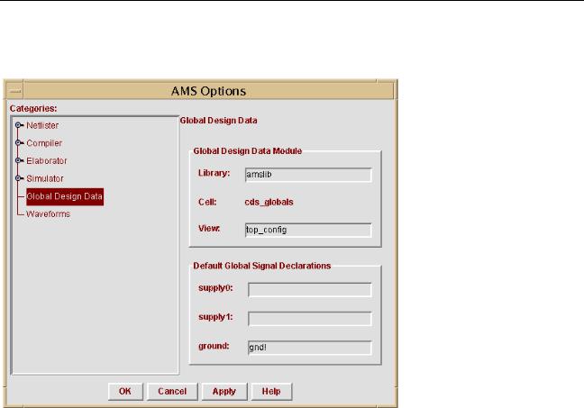
AMS Design Prep automatically generates the cds_globals cell that contains the global signals and design variables. The cell name, cds_globals, is fixed, but you can specify a library name and view name in the Global Design Data Module pane of the window.
The fields in theDefault Global Signal Declarations pane contain lists of signals. AMS Design Prep uses the values in these fields to assign default wire types and to select grounds. For example, if the supply1 field containsvdd! dvdd!, then when AMS Design Prep finds a new global signal nameddvdd!, it declares supply1 as the wire type for dvdd!.
Each list of signals must consist of strings, such as gnd!, vdd!, or agnd!.
April 2004 |
212 |
Product Version 5.3 |
Virtuoso AMS Environment User Guide
Preparing a Design for Simulation
Note that a specification in the AMS Global Signals window overrides, for that signal, the default settings from the Default Global Signal Declarations pane. The AMS Global
Signals window is discussed in the next section.
Specifying Global Signals
Global signals can come from master CDBA (schematic) data or from out-of-module references in master Verilog (digital) or Verilog-AMS HDL data. AMS Design Prep is aware of only global signals that come from master CDBA data. You can use the AMS Global Signals window to declare a signal that is used as an out-of-module signal reference in the master
Verilog (digital) or Verilog-AMS HDL data.
AMS Designer implements global signals as out-of-module references, but does not support out-of-module references either into or out of VHDL-AMS design units. As a result, AMS Designer does not support using global signals in VHDL-AMS design units, even if you enter the VHDL-AMS global signals in the AMS Global Signals window.
When you make changes in the AMS Global Signals window and click OK, AMS Design Prep
■Creates and compiles the cds_globals module if it does not already exist.
■Regenerates and recompiles the cds_globals module if it does already exist.
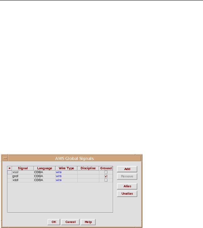
To display the AMS Global Signals window, select AMS – Global Signals.
The display color of the entries in the Signal and Language fields indicates if AMS Design
Prep found the signal, or if you added it. If you added the signal, it is displayed in blue, and if it is found by AMS Design Prep, it is displayed in black.
April 2004 |
213 |
Product Version 5.3 |
Virtuoso AMS Environment User Guide
Preparing a Design for Simulation
The black color means that you cannot remove that signal; you cannot remove a global signal found by AMS Design Prep or add a signal with the same name as a global signal found by
AMS Design Prep. However, if you added a global signal in a previous design session, and it has the same name as a global signal found by AMS Design Prep during the current design session, then the global signal that you added in the previous session is used, and it is displayed in black, so you cannot remove the signal. This behavior is useful when you change the configuration data while switching back and forth between behavioral and schematic views.
If AMS Design Prep cannot find a global signal in the CDBA data in the current run, but found it in a previous run, the signal is displayed in red. You can remove a signal that is displayed in red because it is not needed for the current design configuration.
If the controls are disabled, AMS Design Prep might be unable to write to the cds_globals module where the information in the window is stored. For more information, see “How AMS Design Prep Handles Global Signals and Design Variables” on page 225.
Adding a Global Signal
To add a global signal
1.Click Add.
2.Click in the Signal field for the new line that appears, and type the name of the signal you want to add.
3.Specify the language in which the signal is declared (CDBA, Verilog, Spectre,
SpectreHDL, or SPICE) in the Language field.
4.Choose a wire type from the drop-down menu that appears when you click on the Wire Type field.
You can choose one of the following wire types: wire, tri, wor, wand, trior, trand, trireg, tri0, tri1, supply0, or supply1.
5.Enter the discipline in the Discipline field.
The discipline specification that you enter in this field is written to thecds_globals module. If you do not specify a discipline, no discipline specification is written to the cds_globals file and the discipline of the signal is determined by discipline resolution during elaboration.
For more information, see the “Disciplines” section, in the “Data Types and Objects” chapter, of the Cadence Verilog-AMS Language Reference.
April 2004 |
214 |
Product Version 5.3 |
Virtuoso AMS Environment User Guide
Preparing a Design for Simulation
6.If you want to use the global signal as a ground reference, select the ground option by clicking in the check box in the Ground field for the appropriate signal.
Deleting a Global Signal
To remove a global signal, select the signal by clicking on any field associated with the signal you want to remove, and then click Remove.
Aliasing and Unaliasing Global Signals
You can alias global signals into groups. Aliased signals in a group are electrically equivalent, as if they are joined by a wire. For more information, see “How Aliased Signals Are Netlisted” on page 131.
Aliasing Global Signals
To alias signals
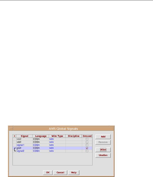
1.Select the signals to be aliased, and click Alias.
To select signals listed consecutively, hold down the shift key while you click on the signal names to be aliased. To select signals that are not listed sequentially, hold down the control key while you click on the signal names. When you alias signals, they redisplay consecutively in the global signal list, joined by a vertical connecting bar, as shown in the example below.
If you alias signals belonging to separate aliased signal groups, all of the signals in the groups are aliased.
April 2004 |
215 |
Product Version 5.3 |