

Virtuoso AMS Environment User Guide
Working with Schematic Designs
Creating Cellviews Using the AMS Environment
This section describes how to create symbol, block, and Verilog-AMS cellviews in the AMS environment.
Preparing a Library
Before you create a cell, you must have a library in which to place it. You can create and store
Verilog-AMS components in any Cadence component library. You can create a new library or use one that already exists.
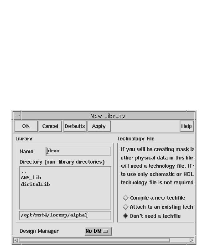
To create a new library,
1.From the Command Interpreter Window (CIW), choose File – New – Library.
The New Library form appears.
2.Type the new library name and directory and click on the radio button for Don’t need a techfile. Click OK.
April 2004 |
152 |
Product Version 5.3 |
Virtuoso AMS Environment User Guide
Working with Schematic Designs
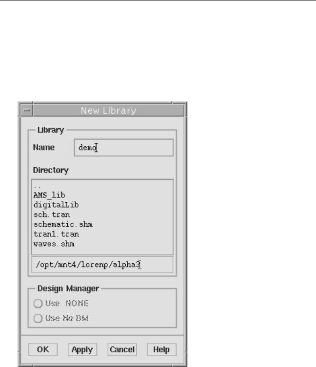
You can also use the Cadence library manager to create a new library.
1.From the CIW, choose Tools – Library Manager.
The library manager appears.
2.Choose File – New – Library.
The New Library form appears. This form is different from the New Library form that you can open from the CIW.
3.In the Name field, type the new library name.
4.In the Directory list box, choose the directory where you want to place the library.
April 2004 |
153 |
Product Version 5.3 |
Virtuoso AMS Environment User Guide
Working with Schematic Designs
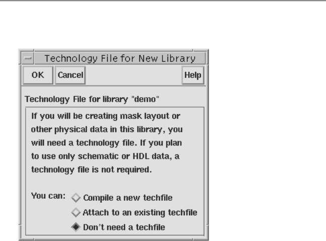
5.Click OK.
A second form appears, asking if you need a technology file for this library.
6.Set Don’t need a techfile on and click OK.
The AMS environment creates a new library with the name you specify in the directory you specify.
April 2004 |
154 |
Product Version 5.3 |

Virtuoso AMS Environment User Guide
Working with Schematic Designs
Creating the Symbol View
To include a Verilog-AMS module in a schematic, you must create a symbol to represent the function described by the module. There are four ways to create this symbol:
■Choose File – New – Cellview from the CIW and specify the target tool as Composer-
Symbol.
■Copy an existing symbol using the Copy command in the library manager. Look in analogLib for good examples to copy.
■Create a new symbol from another view using Design – Create Cellview – From Pin
List or Design – Create Cellview – From Cellview in the Schematic Design Editor.
To create a new symbol this way, you must first have an existing view with defined input and output pins.
■Use a block to represent a Verilog-AMS component, as described in “Using Blocks” on page 155.
However you create the symbol, it must reside in an existing library as described in “Preparing a Library” on page 152.
Pin Direction
The direction you assign to a symbol pin (Verilog-AMS defines pin direction) does not affect that terminal in the Verilog-AMS module. However, if you have multiple cellviews for a component, make sure that the name (which can be mapped), type, and location of pins you assign in a symbol cellview match what is specified in the other cellviews.
Using Blocks
In top-down design practice, you can use blocks to represent Verilog-AMS components. You can create blocks at any level in your design, even before you know how the individual component symbols should look.
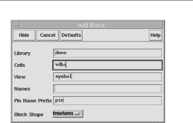
In a schematic, to create a block and wire it, follow these steps:
1. Choose Add – Block in the Virtuoso Schematic Editing window.
April 2004 |
155 |
Product Version 5.3 |
Virtuoso AMS Environment User Guide
Working with Schematic Designs
The Add Block form appears.
2.Type a library name, cell name, and view name.
Specify a cell and view combination that does not exist in that library. You can have schematic, analog HDL, or Verilog-AMS views for that cell, but you cannot already have a symbol view. The default library name is the current library, and the default view name is symbol.
3.(Optional) Specify the pin name seed to use when you connect a wire to the block.
If you specify a seed of pin, the schematic editor names the first pin that you addpin1, names the second pin pin2, and so on.
4.Set the Block Shape cyclic field.
April 2004 |
156 |
Product Version 5.3 |

Virtuoso AMS Environment User Guide
Working with Schematic Designs
5. Place the block as described in the following table.
If Block Shape is set to freeform |
If Block Shape is set to anything else |
Click where you want to place the first corner of the rectangle and drag to the opposite corner. Release the mouse button to complete the block.
Drag the predefined block to the location where you want to place it and click.
Refer to the Virtuoso Schematic Editor User Guide for details about modifying the block samples using the schBlockTemplate variable in the schConfig.il file.
As you place each block, the schematic editor labels it with an instance name. If you leave the Names field of the Add Block form empty, the editor generates unique new names for the blocks.
The editor automatically creates a symbol view for the block.
6.Choose Add – Wire (narrow) or Add – Wire (wide) from the Virtuoso Schematic Editing window menu. When you connect the wire, the pin is created automatically. (To delete such a pin, you must use Design – Hierarchy – Descend Edit to descend into the block symbol.)
The Pin Name Prefix field on the Add Block form specifies the name for the automatically created pin.
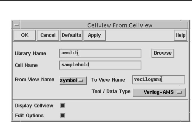
Creating a Verilog-AMS or VHDL-AMS Cellview from a Symbol or Block
Once you have an existing symbol or block, you can create a Verilog-AMS or VHDL-AMS cellview for the function identified by that symbol or block. To create the cellview, follow these steps:
1.Open the Symbol Editor in one of two ways:
From the CIW, choose File – Open and specify the component or block symbol.
From the library manager, choose File – Open or double-click on the symbol view.
2.From the Symbol Editor window, choose Design – Create Cellview – From Cellview.
April 2004 |
157 |
Product Version 5.3 |
Virtuoso AMS Environment User Guide
Working with Schematic Designs
The Cellview From Cellview form appears.
3.In the From View Name cyclic field, choosesymbol.
4.in the Tool / Data Type cyclic list, choose either Verilog-AMS or VHDLAMS, according to the kind of view you want to create.
If you choose Verilog-AMS,
a.In the To View Name field, type a name such asverilogams. To comply with AMS Designer guidelines, the name should be all lower-case.
b.Click OK.
An active text editor window opens, showing the template for a Verilog-AMS module.
//Verilog-AMS HDL for "amslib", "samplehold" "verilogams"
‘include "constants.vams" ‘include "disciplines.vams"
module samplehold ( holdSig, inSig, trigger );
input inSig; input trigger; output holdSig;
endmodule
The AMS environment creates the first few lines of the module based on the symbol information. Pin and parameter information is included automatically.
April 2004 |
158 |
Product Version 5.3 |

Virtuoso AMS Environment User Guide
Working with Schematic Designs
If you choose VHDLAMS, and want to create an architecture,
a.In the To View Name field, type a name such assamplehold_behav. To comply with AMS Designer guidelines, the name should be all lower-case.
b.Click OK.
An active text editor window opens, showing the template for a VHDL-AMS architecture.
--Create Architecture:
--Library=amslib,Cell=samplehold,View=samplehold_behav
--Time:Apr 17 09:32:36 2003
--By:lorenp
ARCHITECTURE samplehold_behav of samplehold IS
BEGIN
END samplehold_behav;
The AMS environment creates the first few lines of the module based on the symbol information.
If you choose VHDLAMS, and want to create an entity,
a.Use the default name of vhdlams in the To View Name field.
b.Click OK.
An active text editor window opens, showing the template for a VHDL-AMS entity.
library ieee, std;
use ieee.std_logic_1164.all; use ieee.electrical_systems.all; entity samplehold is
port ( terminal trigger : electrical; terminal \inSig : electrical; terminal \holdSig : electrical ); end samplehold;
The AMS environment creates the first few lines of the module based on the symbol information.
5.Finish coding the module, then save the file and quit the text editor window.
The AMS environment does not create the cellview until you exit from the editor.
Here is an example of a completed Verilog-AMS module:
//Verilog-AMS HDL for "amslib", "samplehold" "verilogams"
‘include "constants.vams" ‘include "disciplines.vams"
module samplehold ( holdSig, inSig, trigger );
April 2004 |
159 |
Product Version 5.3 |