

Virtuoso AMS Environment User Guide
Working with Schematic Designs
netSet and is a legal net name, its value is used as the connecting net rather than the default net name specified in the expression.
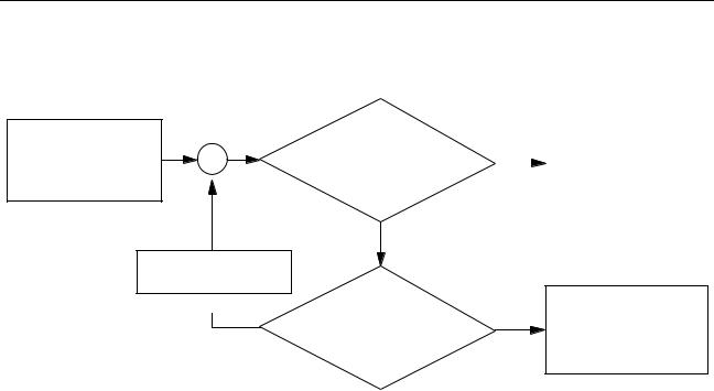
Start at cellview containing net expression
Go up one level
 No
No
Is there a cellview above?
Yes
Is there a netSet property on
the instance of this path?
No |
Use default net name |
||
specified in the net |
|||
|
|
||
|
|
expression |
|
|
|
||
|
|
|
|
Yes
Use value of the netSet property
The netSet property can be placed on any instance and it affects all net expression labels with matching property names at all levels below that instance unless overridden by another netSet property on a lower-level instance.
Net and Pin Properties
The AMS environment supports the following properties. The last three are in addition to those listed in “Properties” on page 610.
netType |
Specifies the type of a net. The type must be one of:supply0, |
|
supply1, tri, tri0, tri1, triand, trior, trireg, wand, |
|
wire, wor, wreal. For example, using the property |
|
netType=wand on net a, results in net a being declared in the |
|
netlist as |
|
wand a; |
netDiscipline |
Specifies the discipline used to declare a net. This is sometimes |
|
called net coercion. For example, using the property |
|
netDiscipline=electrical on net a, results in net a being |
|
declared in the netlist as |
|
electrical a; |
groundSensitivity |
For information, see “groundSensitivity and supplySensitivity |
|
Properties” on page 173 |
April 2004 |
172 |
Product Version 5.3 |

Virtuoso AMS Environment User Guide
Working with Schematic Designs
supplySensitivity For information, see “groundSensitivity and supplySensitivity Properties” on page 173
groundSensitivity and supplySensitivity Properties
The groundSensitivity and supplySensitivity properties provide a way to make a connect module sensitive to supplies in the module to which the connect module is connected.
Typically the port of the connected module is a digital port. It is possible to make a connect module sensitive to supplies in an analog port but making the connect module sensitive to supplies in the connected digital port is much more likely to produce the behavior that you expect. This is so because:
■When the connect module converts analog signals to digital values, the decision to output a one or a zero depends on the relationship between the analog signal and a threshold value. The threshold value is determined by the supply values in the component that includes the connected digital port.
■When the connect module converts digital values to analog signals, the connect module needs to determine what voltage to produce for each digital input value. Again, that voltage depends on the supplies in the component that includes the connected digital port
Overview of the Sensitivity Properties
The groundSensitivity and supplySensitivity properties, which are added to a port or pin definition, have the following syntax.
sensitivity_properties ::=
(* [ integer groundSensitivity = "sig1_sensitive_to" ; ]
[ integer supplySensitivity = "sig2_sensitive_to" ; ] *)
sig1_sensitive_to, sig2sensitive_to
Names of signals, typically global signals, to which a connect module is made sensitive.
When the groundSensitivity property is included as part of a signal declaration in the connect module, the declared signal takes on, by default, the value of sig1_sensitive_to. When the groundSensitivity property is included as part of a signal declaration in an ordinary module, the sig1_sensitive_to value in that module overrides the sig1_sensitive_to value specified in the connect module. The supplySensitivity property works similarly.
April 2004 |
173 |
Product Version 5.3 |

Virtuoso AMS Environment User Guide
Working with Schematic Designs
For example, the connect module might be defined as follows.
connectmodule l_to_e(dval, aval);
...
electrical (* integer groundSensitivity = "global_pwr.pow1" ; *) gnd ;
...
endmodule
This connect module is connected to the digital port d in an ordinary module that is defined as follows.
module sample(d);
output (* integer groundSensitivity = "global_pwr.pow5" ; *) d ;
...
endmodule
In this example, gnd is defined in the connect module as taking on, by default, the value of global_pwr.pow1, but that value is overridden by the value global_pwr.pow5 specified in the module sample when the connect module is inserted across the digital port d. To generalize, if the groundSensitivity property is not used in the ordinary module, the connect module uses the default value specified on thegroundSensitivity property in the connect module.
Basic Principles for Using the Sensitivity Properties
Some basic principles will help you use the groundSensitivity and supplySensitivity properties correctly.
■Connect modules are always inserted between a digital port and an analog net. When you use the groundSensitivity and supplySensitivity properties, you make the connect module sensitive to the signals on the digital port. That is true whatever the direction of the port might be.
■There are two steps involved in establishing ground or supply sensitivity: inserting the necessary properties in the connect module; and adding the corresponding properties to the connected digital port. If the connected digital port is part of a schematic, you define the properties on the connected pin in the schematic. If the connected digital port is defined in a text module, you add the properties to the port definition in the module.
■The default value associated with the groundSensitivity and supplySensitivity properties must be the name of a signal, not the name of a property.
■You must use detailed discipline resolution or the sensitivity properties have no effect.
April 2004 |
174 |
Product Version 5.3 |
Virtuoso AMS Environment User Guide
Working with Schematic Designs
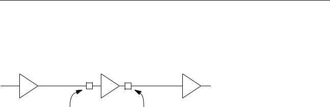
Example: Using the Sensitivity Properties in a Chain of Buffers
Assume that you have the following schematic containing three buffers. Buffers ba1 and ba3 are instances of a module that is implemented as an analog block with analog input and output pins. Buffer bd2 is implemented as a digital block, with logic input and output pins.
ba1 |
bd2 |
ba3 |
n1 |
|
n2 |
elect2logic |
|
logic2elect |
connect module |
|
connect module |
During elaboration, connect modules are inserted across net n1 and the digital input port of buffer bd2, and across the digital output port of buffer bd2 and net n2.
Assume that the string of buffers is designed to run at 5.0 volts. The connect module must then be written to work at that voltage. For example, an A2D connect module with hardcoded thresholds set for 5.0 volts might look like this.
‘include "disciplines.vams" connectmodule elect2logic(aVal, dVal);
output dVal; input aVal; logic dVal; electrical aVal;
reg temp; |
|
|
|
always begin |
|
// Digital, do this always. |
|
if(V(aVal) > |
3.0) |
|
|
#1 |
temp |
= 1; |
// Delay 1 time unit,drive output 1 |
else if |
(V(aVal) < 2.0) |
|
|
#1 |
temp |
= 0; |
// or drive output 0, depending on aVal. |
else |
|
|
|
#1 |
temp |
= 1’bx; |
|
end |
|
|
|
assign dVal = temp; |
// Bind register to digital output. |
||
endmodule
But assume now that the string of buffers can run at either 3.0 volts or 5.0 volts, depending on the supplies that are provided. To make the connect module sensitive to the supplies, you use the groundSensitivity and supplySensitivity properties, and rewrite the always statement so that the threshold is calculated from the supply and ground values.
‘include "disciplines.vams"
connectmodule elect2logic(aVal, dVal); output dVal;
input aVal; logic dVal; electrical aVal;
April 2004 |
175 |
Product Version 5.3 |