

Basic for PIC Microcontrollers (M. Nebojsa, 2001)
.PDFBasic for PIC Microcontrollers |
|
51 |
|
|
|
|
|
|
i2cwrite PORTA.0, PORTA.1, cont, addr, [B0] |
‘ Write value of variable B0 to |
|
|
address 1 |
|
|
|
pause 10 |
‘ Wait 10ms until writing is finished |
|
|
Loop: goto Loop |
|
|
|
end |
|
|
|
|
|
|
4.25 INPUT Designates I/O pin as input
Syntax: |
INPUT Pin |
|
|
|
|
Description: |
INPUT designates the specific pin as input. |
|
|
|
|
Example: |
Main: |
|
|
input PORTA.0 |
‘ Pin PORTA.0 is input. Instruction can be substituted with |
|
TRISB.0=1 |
|
|
TRISB.0=1 |
|
|
Loop: goto Loop |
|
|
end |
|
|
|
|
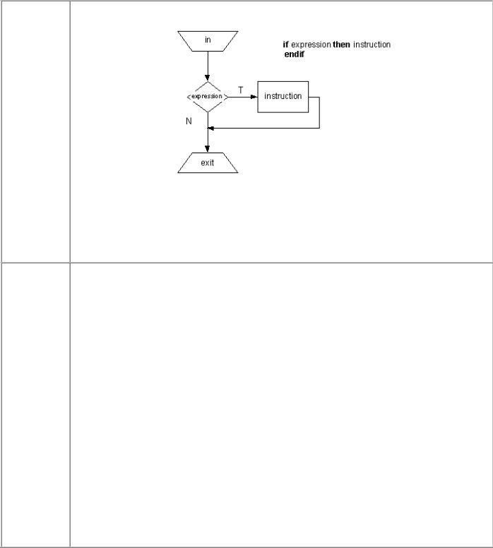
4.26 IF-THEN-ELSE Conditional program branching
Syntax: |
IF Expression1 { AND / OR Expression2} THEN Label |
|
{instructions} |
|
ELSE |
|
{instructions} |
|
ENDIF |
Description: Instruction selects one of two possible program paths. Instruction IF is the fundamental instruction of program branching in PIC BASIC and it can be used in several ways to allow
Basic for PIC Microcontrollers |
52 |
flexibility necessary for realization of decision making logic.
The simplest form of instruction is shown on the picture above. Sample program below tests the button connected to RB0 - when the button is pressed program jumps onto the label “Add” where value of variable “w” is increased. If the button is not pressed, program jumps back onto the label “Main”.
Example:
w var byte
Main :
IF PORTB.0=0 THEN Add goto Main
Add : W=W+1
End
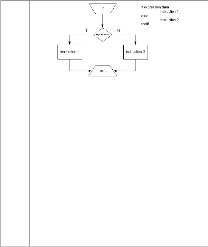
More complex form of instruction is program branching with the ELSE part of instruction.
Basic for PIC Microcontrollers |
53 |
w var byte Main :
IF PORTB.0=0 THEN Add
ELSE Subtract
ENDIF
goto Main Add : W=W+1 Subtract : W=W-1
End
Same effect can be achieved directly :
w var byte

Basic for PIC Microcontrollers |
54 |
Main :
IF PORTB.0=0 THEN W=W+1
ELSE W=W-1
ENDIF
goto Main
End
4.27 LCDOUT Prints data on LCD display
Syntax: |
LCDOUT Data {, Data...} |
Description: LCDOUT sends the data to the LCD (Liquid Crystal Display). PIC BASIC supports various LCD models which have Hitachi 44780 controller or compatible one. LCD usually has either 14 or 16 pins for connection to a microcontroller. If there is character # before data, ASCII value of every data is sent to LCD. LCDOUT has the same modifiers as the instruction SEROUT2.
Modifier |
Sends |
{I}{S} BIN{1..16} |
binary number |
|
|
{I}{S} DEC{1..5} |
decimal number |
|
|
{I}{S} HEX{1..4} |
hexadecimal number |
|
|
REP c/n |
character c repeated n times |
|
|
STR ArrayVar {\n} |
n character string |
|
|
Before the first instruction is sent to LCD, program should wait for at least half a second for LCD to initialize.
LCD display can be connected to PIC microcontrollers by either 4-bit or 8-bit bus. If 8-bit bus is used, all of 8 bits mus t be connected to the same port, while in the case of 4-bit bus all 4 bits must be either in the upper or the lower part of byte. R/W line should be connected to ground if LCD is used only for data display. PIC BASIC assumes that LCD is connected to specific pins if DEFINE directives do not say otherwise. Default is 4-bit bus with lines DB4-DB7 connected to RA0-RA3, RS pin connected to RA4 and E pin connected to RB 3. Also, it is assumed that LCD is 2x16. For changing any of the default settings, appropriate DEFINE directives can be used.

Basic for PIC Microcontrollers |
55 |
If LCD is connected to some other microcontroller lines it has to be defined with DEFINE directives, as shown in the following example.
DEFINE LCD_DREG |
PORTB |
‘ port selection |
DEFINE LCD_DBIT |
4 |
‘ initial bit (0 or 4) selection in case of 4-bit bus |
DEFINE LCD_RSREG |
PORTB |
‘ port Register select |
DEFINE LCD_RSBIT |
1 |
‘ Register Select bit |
DEFINE LCD_EREG |
PORTB |
‘ Enable port |
DEFINE LCD_EBIT |
0 |
‘ Enable bit |
DEFINE LCD_BITS |
4 |
‘ bus size – 4 or 8 bits |
DEFINE LCD_LINES |
2 |
‘ number of LCD lines |
DEFINE LCD_COMMANDS 2000 ‘ command delay in microseconds
DEFINE LCD_DATAUS 50 |
‘ data delay in microseconds |
Definitions above define 2-line LCD on 4 -bit bus on the upper 4 bits of microcont roller port D. Register Select (RS pin) is on PORTD.2 and Enable is on PORTD.3.
Every LCD controller is in charge of certain commands. Commands are sent by instruction: LCDOUT $FE, $Kod. List of commands is shown in table below.
Command |
Operation |
$FE, 1 |
clear display |
|
|
$FE, 2 |
Return home (beginning of the first line) |
$FE, $0C |
Turn off cursor |
|
|
$FE, $0E |
Underline cursor on |
$FE, $0F |
Blinking cursor on |
$FE, $10 |
Shifting cursor left |
|
|
$FE, $14 |
Shifting cursor right |
Basic for PIC Microcontrollers |
|
|
|
56 |
|
|||
|
|
|
|
|
|
|
|
|
|
|
|
$FE, $C0 |
|
|
|
set cursor to the beginning of the second line |
|
|
|
|
$FE, $94 |
|
|
|
set cursor to the beginning of the third line |
|
|
|
|
|
|
|
|
|
|
|
|
|
$FE, $D4 |
|
|
|
set cursor to the beginning of the fourth line |
|
|
|
|
|
|
|
|
|
|
|
|
|
|
|
|
|
|
|
Example: |
|
|
|
|
|
|
|
|
|
B0 var byte |
|
|
|
|
|
|
|
|
B1 var byte |
|
|
|
|
|
|
|
|
Main: |
|
|
|
|
|
|
|
|
|
lcdout |
$FE, 1, “Hello” |
|
‘ Clear display and print “Hello” |
|
||
|
|
lcdout |
$FE, $C0 |
‘ |
switch to second line |
|
||
|
|
lcdout |
B0 |
|
|
‘ |
Display the value of B0 |
|
|
|
lcdout |
#B1 |
|
|
‘ |
Display the value of B1 in ASCII code |
|
|
Loop: goto Loop |
|
|
|
|
|
||
|
|
end |
|
|
|
|
|
|
|
|
|
|
|
|
|
|
|
4.28 LCDIN Reads data from LCD RAM
Syntax: |
LCDIN {Address,} [Var{, Var...}] |
|
|
|
|
Description: |
LCDIN reads the given address of LCD RAM and stores data into a variable. When using |
|
|
this instruction, LCD Read/Write line must be connected to microcontroller. In case when |
|
|
LCD is used for data printing exclusively, this line can be connected to a logical zero. |
|
|
DEFINE directives inform the program about port and pin which Read/Write line is |
|
|
connected to: |
|
|
DEFINE LCD_RWREG PORTE |
‘ LCD read/write port |
|
DEFINE LCD_RWBIT 2 |
‘ LCD read/write bit on port |
|
|
|
Example: |
B0 var byte |
|
|
Main: |
|
|
Lcdin $40, B0 ‘ Read data from LCD location $40 and store it into B0 |
|
|
|
|

Basic for PIC Microcontrollers |
57 |
Loop: goto Loop
End
4.29 {LET} Puts the value of the expression into a variable
Syntax: |
{LET} {Var=Expression} |
Description: LET instruction stores value of the expression into a variable. Expression can be a constant, variable or value of some other expression. Commonly, the optional command word LET is excluded.
Example:
let B0 = B1 * B2 + B3
B0 = B1 * B2 + B3
The two expressions are identical. The latter expression is missing command word “let”.
4.30 LOOKDOWN Searches the table of constants
Syntax: |
LOOKDOWN Value, [Const {, Const...}], Var |
Description: Instruction LOOKDOWN searches the list of constants and determines the presence of given value. If a given value matches some of the constants, index of the appropriate constant is stored into variable. If the first constant matches our given value, variable is set to zero. If the second constant from the list matches our given value, variable is set to one, etc. If our value isn’t present in the list, variable remains unchanged. Constants list can consist of both numerical and character (string) values. Each character of a string is treated as a separate ASCII value of a constant.
Example: |
B0 var byte |
|
B1 var byte |
|
B0=$f |

Basic for PIC Microcontrollers |
58 |
Main:
lookdown B0, (“01234567890ABCDEF”), B1 ‘ convert hexadecimal character from B0 to a decimal value and store it into variable B1
PORTB=B1 ‘ PRIKAZI number on port B diodes
loop: goto loop
End
4.31 LOOKDOWN2 Searches the table of constants/variables
Syntax: |
LOOKDOWN2 Search, {Test} [Value {, Value...}], Var |
Description: LOOKDOWN2 searches the list of values and determines the presence of given value. If “Search” value matches some of the “Value” values, index of the appropriate constant is stored into “Var”.
If “Search” matches the first value of the list, “Var” set to zero. If it matches the second value of the list, “Var” is set to one, etc. If “Search” va lue isn’t present in the list, “Var” remains unchanged.
Optional parameter “Test” is used for testing if “Search” value is greater or lesser than a certain value. If “>” is used, index of the first matching constant is stored to “Var”. List of values can consist of 16-bit numbers, characters or variables. Every character of a string is treated as a separate ASCII value of that character (arrays of variables cannot be used with LOOKDOWN2 instruction). LOOKDOWN2 generates the code about 3 times greater than LOOKDOWN instruction does. Thus, when searching the list consisting of 8-bit constants and strings, use of LOOKDOWN is prefferrable.
Example:
lookdown2 W0, [512, 768, 1024], B0
If value of W0 is 512 B0 will have value of 0. If value of W0 is 768 then B0 will have value of 1, etc.

Basic for PIC Microcontrollers |
59 |
lookdown2 W0, <[10,100,1000], B0
If value of W0 is 4 B0 will have value of 0. If value of W0 is 200 then B0 will have value of 2, etc.
4.32 LOOKUP Gets value from the table of constants
Syntax: |
LOOKUP Index, ( Constant {, Constant}), Var |
|
|
|
|
Description: |
LOOKUP is used for reading values from the table of constants, according to the value of |
|
|
variable “Index”. If “Index” equals zero, “Var” is set to the value of the first constant. If |
|
|
“Index” equals one, “Var” is set to the value of the second constant, etc. If “Index” is |
|
|
equal or greater than number of elements in the Look-up table “Var” remains unchanged. |
|
|
List of constants can consist of numerical and string constants. Each character of a string |
|
|
is treated as a separate ASCII value of a character. |
|
|
|
|
Example: |
Program below illustrates the use of LOOKUP instruction. for displaying digits on seven- |
|
|
segment displays. Depending on value of parameter “Digit”, we get mask for appropriate |
|
|
value of parameter “mask”. |
|
|
Digit var byte |
‘ value of digit to be displayed |
|
Mask var byte‘ |
mask of digit to be displayed |
|
Main: |
|
|
for i=0 to 9 |
|
|
Digit=i |
|
|
Lookup Digit, [$3F, $06, $5B, $4F, $66, $6D, $7D, $07, $7F, $6F], Mask |
|
|
PORTB=Mask |
‘ Send the mask of a digit to port B |
|
pause 500 ‘ |
delay allowing to see digits changing |
|
|
|
Basic for PIC Microcontrollers |
60 |
|
|
|
|
|
next i |
‘ Increase i by one |
|
goto Main |
‘ Repeat the whole program |
|
end |
|
|
|
|