

Basic for PIC Microcontrollers (M. Nebojsa, 2001)
.PDFBasic for PIC Microcontrollers |
41 |
FREQOUT works best with a 20 MHz oscillator (while it is more difficult to filter the signal for the lower frequencies). "Onms" represents the duration of the signal in milliseconds.
In order to obtain the desired sinusoidal signal at output, the installation of a sort of filter is required.
Example:
4.16 FOR-NEXT Repeating of the program segment
Syntax: |
FOR Index = Start TO End {Step {-} Inc } |
|
{ instructions, |
|
instructions } |
|
NEXT {Index} |
|
|
Description |
The instructions of repeating one or more instructions. The conducting expression will |
: |
determine how many times will repeating take place. "Index" is usually the variable |
|
employed for the control of how many times is for...next loop executed. If the parameter |
|
"Step" is not specified, it is understood that the variable "Index" is increased by one. |
|
(Index = Index + 1). |
|
|
Example: |
auxiliary variable |
|
the program turns on and off |
|
the diodes at port B with 1s |
|
pause 200 times. |
|
auxiliary variable |
|
|

Basic for PIC Microcontrollers |
42 |
the program turns on and off the diodes at port B with 1s pause 100 times
auxiliary variable
the program turns on and off the diodes at port B with 1s
pause 900 times

Basic for PIC Microcontrollers |
43 |
INSTRUCTIONS (2/4)
Introduction |
|
|
|
4.1 @ |
4.17 GOSUB |
4.33 LOOKUP2 |
4.49 RETURN |
4.2 ASM..ENDASM |
4.18 GOTO |
4.34 LOW |
4.50 REVERSE |
4.3 ADCIN |
4.19 HIGH |
4.35 NAP |
4.51 SELECT-CASE |
4.4 BRANCH |
4.20 HSERIN |
4.36 OUTPUT |
4.52 SERIN |
4.5 BRANCHL |
4.21 HPWM |
4.37 OWIN |
4.53 SERIN2 |
4.6 BUTTON |
4.22 HSEROUT |
4.38 OWOUT |
4.54 SEROUT |
4.7 CALL |
4.23 I2CREAD |
4.39 PAUSE |
4.55 SEROUT2 |
4.8 CLEAR |
4.24 I2CWRITE |
4.40 PAUSEUS |
4.56 SHIFTIN |
4.9 CLEARWDT |
4.25 INPUT |
4.41 POT |
4.57 SHIFTOUT |
4.10 COUNT |
4.26 IF-THEN-ELSE |
4.42 PULSIN |
4.58 SLEEP |
4.11 DATA |
4.27 LCDOUT |
4.43 PULSOUT |
4.59 SOUND |
4.12 DTMFOUT |
4.28 LCDIN |
4.44 PWM |
4.60 STOP |
4.13 EEPROM |
4.29 {LET} |
4.45 RANDOM |
4.61 SWAP |
4.14 END |
4.30 LOOKDOWN |
4.46 RCTIME |
4.62 TOGGLE |
4.15 FREQOUT |
4.31 LOOKDOWN2 |
4.47 READ |
4.63 WRITE |
4.16 FOR-NEXT |
4.32 LOOKUP |
4.48 READCODE |
4.64 WRITECODE |
|
|
|
4.65 WHILE-WEND |
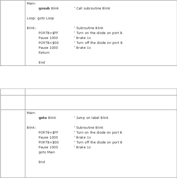
4.17 GOSUB Calls BASIC subroutines
Syntax: |
GOSUB label |
Description: Executes the PBP instructions of the program which are situated between label "label" and instruction RETURN. When program encounters the RETURN, the execution of the program goes on with the instruction line that follows GOSUB instruction. Part of the program code between the label and the RETURN instruction is commonly called subroutine.
Subroutine can be "nested". In other words, it is possible that the subroutine calls some other program. Such programming should n‘t go beyond four levels depth because of the finite size of the PIC microcontroller stack.
Basic for PIC Microcontrollers |
44 |
Example:
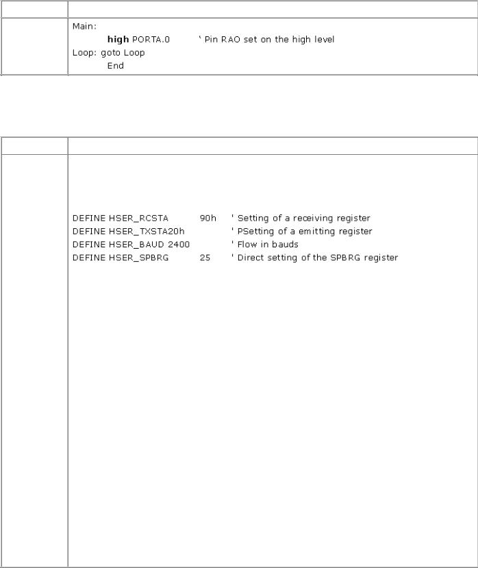
4.18 GOTO Continues the execution of the program on a certain label
Syntax: |
GOTO label |
Description: The execution of the program continues with the instruction line following the label "label". It is not recommended to use this command too often, because over-labeled programs are generally less intelligible.
Example:
The program above does exactly the same thing as the previous one, but without GOSUB instruction.
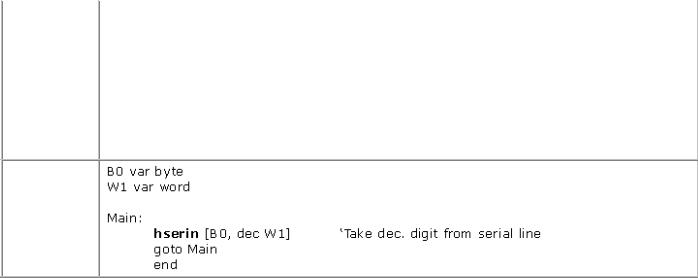
4.19 HIGH |
Sets a logical "1" on the output pin |
|
|
|
|
Syntax: |
|
HIGH Pin |
|
|
|
Basic for PIC Microcontrollers |
45 |
Description: Sets the appropriate pin on the high level. Pin is thereby automatically designated output.
Example:
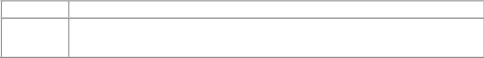
4.20 HSERIN Hardware asynchronous serial inp ut
Syntax: |
HSERIN {Error,}{Timeout, Label,}[Modifier(,...)] |
Description: HSERIN receives one or more serial data. It can be used with PIC microcontrollers which have hardware supported serial communication, i.e. in those which have hardware USART (e.g. microcontroller 16F877). The parameters of serial transfer are determined at the beginning of the program with the following DEFINE directives :
HSERIN operates with 4 MHz oscillators by default. If the microcontroller is connected with an oscillator of a different frequency it has to be specified :
DEFINE OSC tact ‘ Specific oscillator frequency
Putting the parameters "Timeout" and "Label" enables the continuation of the program even with receiving no character in the course of a "Timeout" interval (specified in milliseconds). Format of the serial data 8N1 (8 bits of the data, without a parity bit and with only one stop bit). Some other formats, such as 7E1 (7 bits of data, parity bit and 1 stop bit) can be used with the previous changes through DEFINE at the beginning of program.
DEFINE HSER_EVEN |
1 |
‘ Only when we want to check the parity. |
DEFINE HSER_ODD |
1 |
‘ Only when we want to check the non-parity. |
The program may also contain the optional label "Error" at which the program jumps in case of error in transfer or the violation of parity. Label "Error" is used only if the check of parity/non-parity is in advance enabled with the corresponding DEFINE directions. The serial transfer is done by hardware so that for an adapting on RS-232 an additional inverting driver is necessary. Modifiers in HSERIN are the same as by the command SERIN2.
Modifier |
How it works |
BIN{1..16} |
Takes binary digits |
|
|
DEC{1..5} |
Takes decimal digits |
|
|
Basic for PIC Microcontrollers |
46 |
|
|
|
|
|
|
|
|
|
|
|
HEX{1..4} |
Takes hexadecimal digits |
|
|
SKIP n |
Doesn‘t take next n characters |
|
|
STR ArrayVar\n{\c} |
Takes the sequence of n characters that ends with the |
|
|
character c (optional) |
|
|
|
|
|
|
|
|
|
|
|
WAIT ( ) |
waits for character sequence |
|
|
WAITSTR ArrayVar{\n} |
waits for a string |
|
|
|
|
|
Example:
4.21 HPWM Generates PWM signal on the microcontroller pin
Syntax: |
HPWM Channel,Relation_on_off, Frequency |
||
|
|
||
Description: |
Command uses the hardware PWM on the microcontrollers who possess it for the |
||
|
generation of the PWM signal. |
|
|
|
The parameter "channel" defines the exact PWM channel that is to be used. In the two |
||
|
channel microcontrollers, the parameter "frequency" must be identical on both of them. |
||
|
The parameter "Relation_on_off" defines the relation between on and off signals on the |
||
|
pin. Value 0 sets the pin to always off, while 255 sets it to always on. All other values in |
||
|
the interval 0~255 define the appropriate ODNOS of on and off signals on the pin (for |
||
|
example, value 127 sets 50% on and 50% off signal). |
||
|
Parameter "Frequency" defines the frequency of the PWM signal (highest possible |
||
|
frequency for any oscillator is 32767 Hz) which depends on oscillator used. Lowest |
||
|
frequency depends on oscillator used. |
||
|
If not specified otherwise, PWM generates 0 timer by default. |
||
|
|
|
|
Example: |
DEFINE HPWM2_TIMER 1 |
‘ |
second channel uses timer 1 |
|
hpwm 2, 64, 1000 |
‘ |
25% PWM on 1kHz |
|
|
|
|
4.22 HSEROUT Hardware asynchronous serial output

Basic for PIC Microcontrollers |
47 |
|
|
|
|
Syntax: |
HSEROUT [Item{,Item...}] |
|
Description: HSEROUT sends one or more serial data and is used in the PIC microcontrollers that have hardware supported serial communication (hardware USART). Parameters of serial transfer are determined by with the following DEFINE directives:
DEFINE HSER_RCSTA 90h |
‘ |
Setting the receiving register |
DEFINE HSER_TXSTA 20h |
‘ |
Setting the emitting register |
DEFINE HSER_BAUD 2400 |
‘ Baud rate |
|
DEFINE HSER_SPBRG 25 |
‘ |
Direct setting of SPBRG |
When calculating transfer rate, HSERIN assumes that microcontroller works with the 4MHz oscillator. If different oscillator is used, new frequency must be specified with the following directive:
DEFINE OSC ‘ Specific oscillator frequency
Format of serial data is 8N1 - 8 data bits, with no parity bit and with 1 stop bit. Some other formats, such as 7E1 (7 data bits, parity bit, 1 stop bit) or 7O1 (7 data bits, nonparity bit, 1 stop bit) may be used with the following DEFINE directives at the beginning of the program:
|
|
DEFINE HSER_EVEN 1 |
‘ |
Only when we want to verify the parity |
|
|
|
|
DEFINE HSER_ODD 1 |
‘ |
Only when we want to verify the non -parity |
|
|
|
Serial transfer is hardware based, so you might need an additional driver for adjusting to |
|
||||
|
RS-232 (MAX232). |
|
|
|
|
|
|
|
|
|
|
|
|
|
|
Modifier |
|
|
Sends |
|
|
|
{I}{S} BIN{1..16} |
|
|
binary number |
|
|
|
|
|
|
|
|
|
|
{I}{S} DEC{1..5} |
|
|
decimal number |
|
|
|
|
|
|
|
|
|
|
{I}{S} HEX{1..4} |
|
|
hexadecimal number |
|
|
|
|
|
|
|
|
|
|
REP c/n |
|
|
character c repeated n times |
|
|
|
|
|
|
|
|
|
|
STR ArrayVar {\n} |
|
n character string |
|
|
|
|
|
|
|
|
|
Example: |
|
B0 var byte |
|
|
|
|
|
|
B0 = 4 |
|
|
|
|
|
|
Main : |
|
|
|
|
|
|
hserout [dec B0, 10] ‘ send decimal number from variable B0 and constant |
|
|||

Basic for PIC Microcontrollers |
48 |
10
Loop: goto Loop
end
4.23 I2CREAD Reading data from I2C peripheral device
Syntax: |
I2CREAD Data, Frequency, Control_byte, {Address,} [Variable {, Variable...}]{,Label} |
Description: Sends control and address data via I2C lines and receieved bytes are stored into "Variable".
I2CREAD and I2CWRITE can be used for reading and writing data to peripheral units. These instructions work with I2C master byte in read and write modes and can be also used for communication with other devices with I2C interface, such as temperature sensors, A/D converters, etc.
Higher 7 bits of control byte contain control code for chip selection or extra information on addresses, depending on device. The lowest bit is flag indicating the current mode - read or write.
For example, for communicating with 24LC01B, requested address is 8-bit, control code is %1010 and chip select is unused, so that control byte would be %10100000 or $A0.
Formats of control bytes for several other serial EEPROMs are given in the table below:
EEPROM |
Capacity |
Control word |
Address size |
24LC01B |
128 bytes |
%1010xxx0 |
1 byte |
24LC02B |
256 bytes |
%1010xxx0 |
1 byte |
|
|
|
|
24LC04B |
512 bytes |
%1010xxb0 |
1 byte |
24LC08B |
1K bytes |
%1010xbb0 |
1 byte |
|
|
|
|
24LC16B |
2K bytes |
%1010bbb0 |
1 byte |
|
|
|
|
24LC32B |
4K bytes |
%1010ddd0 |
2 bytes |
|
|
|
|
24LC65 |
8K bytes |
%1010ddd0 |
2 bytes |
|
|
|
|
bbb= block selection
ddd = device selection bits xxx = has no effect
If 2-byte data (WORD) is received, higher byte is received first, and lower thereafter. For
Basic for PIC Microcontrollers |
49 |
||
|
|
||
|
string transfer, STR goes before the name of the string, and number of clocks after \ . |
||
|
a var byte[8] |
|
|
|
I2CREAD PORTC.4, PORTC.3, $a0, 0, [STR a\8] |
||
|
If optional label is used, program will jump to the label if there is no response signal over |
||
|
the I2C interface. Standard transfer rate (100kHz) is achieved with 8MHz oscillator. For |
||
|
higher transfer rate (400kHz) 20MHz oscillator is used. If slower oscillator is used for the |
||
|
transfer, following directive should be used : |
||
|
DEFINE I2C_SLOW 1 |
|
|
|
In order to have bipolar I2C clock interface and not an open collector, following DEFINE |
||
|
directive should be used: |
|
|
|
DEFINE I2C_SCLOUT |
|
|
|
Operating any peripheral units with I2C communication demands that you read supplier |
||
|
manuals and specifications. |
||
|
|
|
|
Example: |
B0 var byte |
|
|
|
addr var |
byte |
|
|
cont con |
%10100000 ‘ |
Control address of EEPROM |
|
addr = 17 |
‘ |
Data address is 17 |
|
Main: |
|
|
|
I2CREAD PORTA.0, PORTA.1, cont, addr, [B0] ‘ Get data to variable B0 |
||
|
Loop: goto Loop |
|
|
|
end |
|
|
|
|
|
|
4.24 I2CWRITE Writing data to I2C peripheral device
Syntax: |
I2CWRITE Data, Frequency, Control_byte, {Address,} [Vari {, Vari...}]{,Label} |
Description: I2WRITE sends control and address data via I2C interface. We define 8-bit or 16-bit address while defining variable put to address parameter (in order to correctly define address size, we must have accurate information on device we are communicating with).

Basic for PIC Microcontrollers |
50 |
If peripheral device is serial EEPROM, it is necessary to wait for 10ms (depending on device) until writing has ended. New communication with device is possible after 10ms have elapsed. If new data write occurs before the last one has ended, request will be ignored. Address size is either 1 or 2 bytes, depending on device connected. A problem may occur when trying to write multiple bytes in one instruction, depending on specific EEPROM. Such instances can be avoided if, instead of EEPROM, we use devices without the need for pause between writing. If 2-byte data (WORD) is sent, higher byte goes first, then the lower. For string transfer, STR goes before the name of the string, and number of clocks after \ .
a var byte[8]
I2CWRITE PORTC.4, PORTC.3, $a0, 0, [STR a\8]
If optional label is used, program will jump onto the label if there is no response signal over the I2C interface. Standard transfer rate (100kHz) is achieved by 8MHz oscillator. For higher transfer rate (400kHz) 20MHz oscillator is used. If slower oscillator is used for the transfer program should contain the following directive:
DEFINE I2C_SLOW 1
In order to have bipolar I2C clock interface and not an open collector, following DEFINE directive should be used:
DEFINE I2C_SCLOUT
Operating any peripheral units with I2C communication requires that you study the supplier manual and specifications.
Example: |
B0 var byte |
|
|
|
|
addr var |
byte |
|
|
|
cont con |
%10100000 ‘ |
Control address of EEPROM |
|
|
Main: |
|
|
|
|
addr = 17 |
‘ |
EEPROM address where data will be written is 17 |
|
|
i2cwrite PORTA.0, PORTA.1, cont, addr, [6] ‘ Write number 6 to address 17 |
|||
|
pause 10 |
‘ |
Wait 10ms until writing is finished |
|
|
addr = 1 |
‘ |
Set address of writting to 1 |
|
|
B0 = 23 |
|
|
|