

Basic for PIC Microcontrollers (M. Nebojsa, 2001)
.PDFBasic for PIC Microcontrollers |
91 |
Chapter 5
SAMPLE PROGRAMS FOR SUBSYSTEMS WITHIN THE MICROCONTROLLER
Introduction
5.1 Using the interrupt mechanism
5.2 Using the internal AD converter
5.3 Using the TMR0 timer
5.4 Using the TMR1 timer
5.5 Using the PWM subsystem
5.6 Using the hardware UART subsystem (RS-232 communication)
Introduction
Every microcontroller is supplied with at least a few integrated subsystems - commonly, these include timers, interrupt mechanisms and AD converters. More powerful microcontrollers can command greater number of built-in subsystems. Some of frequently encountered systems are detailed in this chapter.
5.1 Using the interrupt mechanism
Interrupts are mechanisms which enable instant microcontroller response to events such as : TMR0 counter overflow, state changes on RB0/INT pin, data is received over serial communication, etc. With bigger microcontrollers, number of interrupt sources is even greater. In normal mode, microcontroller executes the main program as long as there are no occurrences that would cause interrupt. When interrupt does take place microcontroller stops the execution of the main progra m and starts executing part of the program (interrupt routine) that will analyze and handle the interrupt. Analysis in necessary because PIC microcontrollers call the same interrupt routine in response to any of the mentioned events. Therefore, the first task is to determine which event caused the interrupt. After the analysis comes the interrupt handling, which is executing the appropriate part of program code tied to a certain event.
Basic for PIC Microcontrollers |
92 |
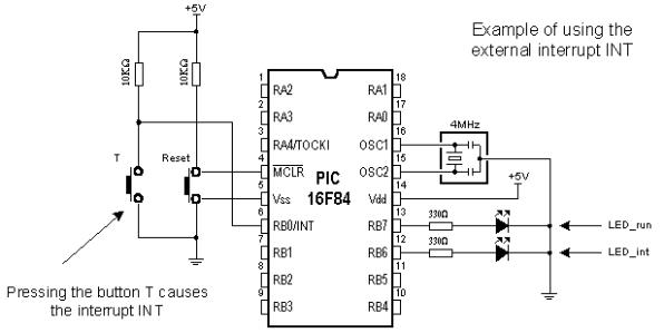
Button T is connected to the external interrupt input INT (pin RB0/INT) so that pressing the button is considered an interrupt occurrence. In order to see the change caused by interrupt LED diodes are connected to the pins RB6 and RB7. LED_run diode signalizes that the main program is being executed, while LED_ini diode signalizes the interrupt caused by pressing the button T. Following instructions are used in PIC BASIC programs which contain interrupt routine :
On Interrupt goto Address Defines the interrupt vector (address of interrupt routine)
Disable |
Disables the interrupts |
Enable |
Enables the interrupts |
Resume |
Return to the main program after handling the event |
Following example demonstrates usage of external interrupt INT located on pin RB0. At the same time, program gives an example how to handle multiple interrupt sources.
Basic for PIC Microcontrollers |
93 |
Basic for PIC Microcontrollers |
94 |
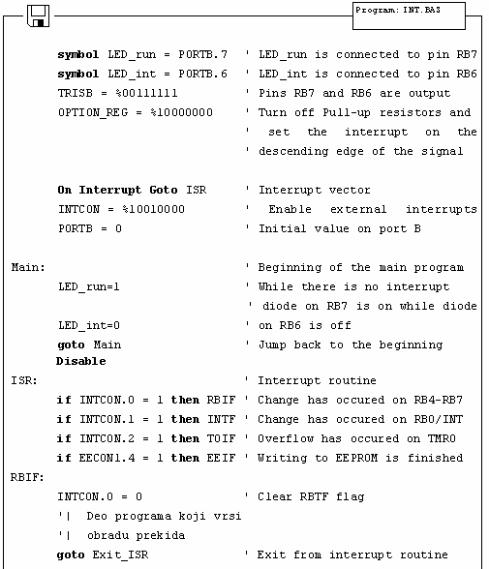
Program which handles interrupt must have the main loop (program) and an interrupt routine. Program in the main loop keeps
LED_run diode on and LED_int diode off. Pressing the button T causes the interrupt and the microcontroller will stop executing the main program and start executing the interrupt routine ISR marked by On interrupt instruction.
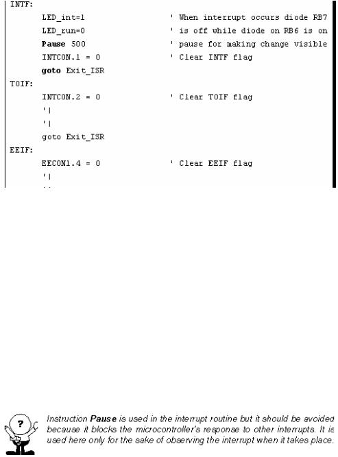
At the beginning of the interrupt routine there is instruction Disable. This instruction disables all interrupts until handling the current interrupt is over. ISR routine then analyses the interrupt by checking bits (flags) set on "1" with couple of if...then instructions, because there are several possible interrupt causes. In our case, an external interrupt took place (pin RB0/INT state changes) and therefore bit INTF in INTCON register is set and the microcontroller continues program execution from the label INTF. Part of the program code following the label INTF handles the interrupt and resets INTF bit in order to enable interrupts again. In this case, handling the external INTinterrupt changes state of diodes LED_int and LED_run : it turns off LED_run and turns on LED_int for half second period. After INTF is being reset, microcontroller continues executing the program from Exit_ISR label where interrupts are enabled (instruction Enable) and microcontroller returns to executing the main program (instruction Resume).
Why use interrupts at all ? In situations where the microcontroller must respond to events unrelated to the main program it is very useful to have an interrupt. Perhaps, one of the best examples is multiplexing the seven-segment display. If multiplexing code is part of the interrupt routine tied to timer interrupt the main program will be much less burdened because display refreshing will work in the background of the main program.
5.2 Using the internal AD converter
Certain microcontrollers have built in analog-digital converter (abbrev. ADC). Usually, these AD converters do not exceed 8 to 10 bits resolution allowing them voltage sensitivity of 19.5mV with 8-bit resolution and 4.8mV with 10-bit resolution (assuming that default
Basic for PIC Microcontrollers |
95 |
5V voltage is used).
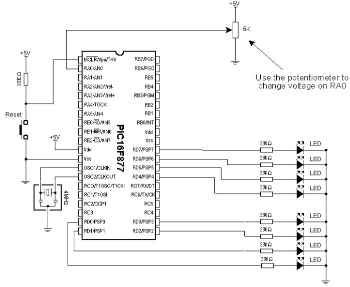
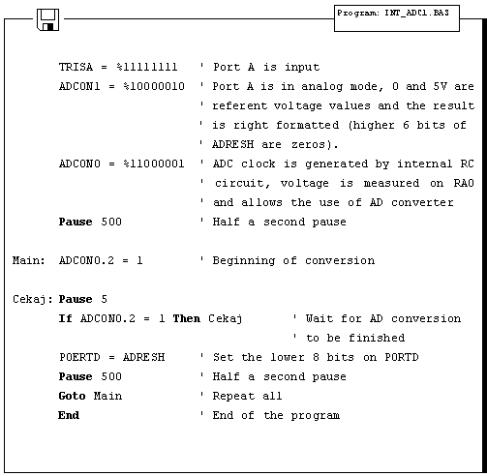
The simplest AD conversion program would use 8-bit resolution and 5V of microcontroller power as referent voltage (value which the value "read" from the microcontroller pin is compared to). In the following example we measure voltage on RA0 pin which is connected to the potentiometer (picture below).
Potentiometer gives 0V in one terminal position and 5V in the other, so that digitalized voltage can take values ranging from 0 to 256 due to the fact that 8-bit conversion is used. The following program reads voltage on RA0 pin and displays it on port B diodes. If not one diode is on, result is zero and if all of diodes are on, result is 255.
Basic for PIC Microcontrollers |
96 |
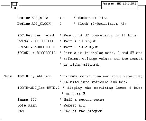
At t he very beginning, it is necessary to properly initialize 2 bit registers ADCON1 and ADCON0. Afterwards, only thing required is to set ADCON0.2 bit which initializes the conversion and checks ADCON0.2 to determine if conversion is over. After the conversion is over, result is stored into ADRESH and ADRESL where from it can be copied. Former example can also be carried out via ADCIN instruction. Following example uses 10-bit resolution and ADCIN instruction.
Basic for PIC Microcontrollers |
97 |
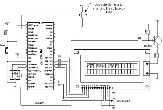
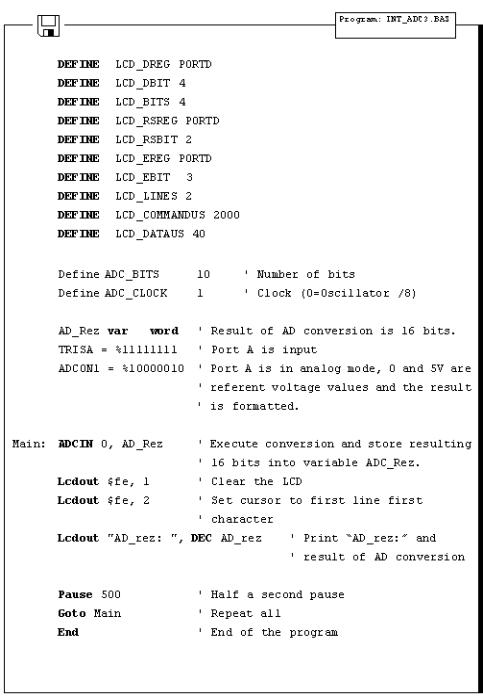
As one port is insufficient, LCD can be used for displaying all of the 10 bits of result. Connection scheme is on the picture below and appropriate program follows.
Basic for PIC Microcontrollers |
98 |
Basic for PIC Microcontrollers |
99 |
5.3 Using the TMR0 timer
TMR0 timer is 8 -bit and has working range of 255. Assuming that 4MHz oscillator is used, time period TMR0 can measure falls into 0-256 microseconds range (with 4MHz frequency TMR0 increments by one microsecond). If prescaler is used that period can be
Basic for PIC Microcontrollers |
100 |
prolonged, because prescaler divides the clock in a certain ratio (prescaler settings are made in OPTION_REG register).
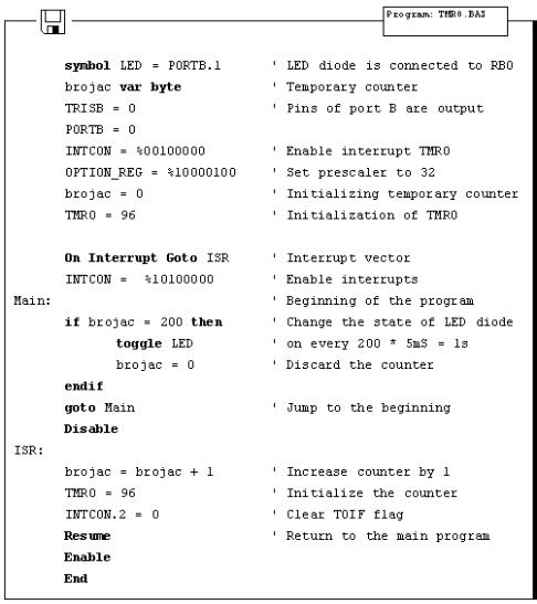
Following program illustrates use of TMR0 timer for generating 1 second time period. Prescaler is set to 32, so that internal clock is divided by 32 and TMR0 increments every 31 microseconds. If TMR0 is initialized on 96, overflow occurs in (256-96)*31 us = 5 ms.
If variable "Brojac" is increased every time interrupt takes place, we can measure time according to the value of variable "Brojac". If "Brojac" is set to 200, time will total 200*5 ms = 1 second.
Before the main program, TMR0 should have interrupt enabled (bit 2) and GIE bit (bit 7) in INTCON register should be set.
5.4 Using the TMR1 timer
Unlike TMR0, TMR1 is 16-bit and has working range of 65536. Assuming that 4MHz oscillator is used, time period TMR1 can