

Basic for PIC Microcontrollers (M. Nebojsa, 2001)
.PDFBasic for PIC Microcontrollers |
121 |
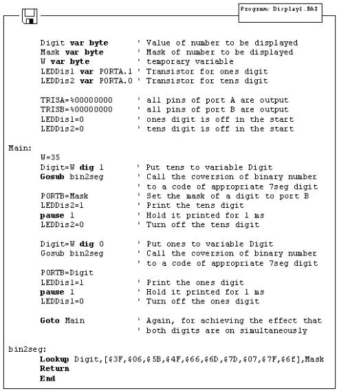
Variables LEDDisp1 and LEDDisp2 are actually pins 1 and 0 of port A, which bases of transistors T1 and T2 are connected to. Setting logical one on those pins turns on the transistor, allowing every segment from "a" to "h", with logical one on it, to emit light. If there is logical zero on transistor base, none of the segments will emit light, regardless of the pin state. Tens digit is disabled at the very beginning of program, ahead of label Main (LEDDisp2=0).
Purpose of the program is to display figures from 0 to 9 on the ones digit, with 0.5 seconds pause in between. In order to display any number, it's mask must be sent to port B. For example, if we need to display "1", segments "b" and "c" must be set to 1 and the rest must be zero. If (according to the scheme above) segments b and c are connected to the first and the second pin of port B, values 0000 and 0110 should be set to port B. These values which are set to port are commonly called "masks". Mask for number "1" is value 0000 0110 or $06 (hexadecimal). The following table contains corresponding mask values for numbers 0-9 :
Digit |
Seg. h |
Seg. g |
Seg. f |
Seg. e |
Seg. d |
Seg. c |
Seg. b |
Seg. a |
HEX |
|
|
|
|
|
|
|
|
|
|
0 |
0 |
0 |
1 |
1 |
1 |
1 |
1 |
1 |
$3F |
|
|
|
|
|
|
|
|
|
|
1 |
0 |
0 |
0 |
0 |
0 |
1 |
1 |
0 |
$06 |
|
|
|
|
|
|
|
|
|
|
2 |
0 |
1 |
0 |
1 |
1 |
0 |
1 |
1 |
$5B |
|
|
|
|
|
|
|
|
|
|
3 |
0 |
1 |
0 |
0 |
1 |
1 |
1 |
1 |
$4F |
|
|
|
|
|
|
|
|
|
|
4 |
0 |
1 |
1 |
0 |
0 |
1 |
1 |
0 |
$66 |
|
|
|
|
|
|
|
|
|
|
5 |
0 |
1 |
1 |
0 |
1 |
1 |
0 |
1 |
$6D |
|
|
|
|
|
|
|
|
|
|
6 |
0 |
1 |
1 |
1 |
1 |
1 |
0 |
1 |
$7D |
|
|
|
|
|
|
|
|
|
|
7 |
0 |
0 |
0 |
0 |
0 |
1 |
1 |
1 |
$07 |
|
|
|
|
|
|
|
|
|
|
8 |
0 |
1 |
1 |
1 |
1 |
1 |
1 |
1 |
$7F |
|
|
|
|
|
|
|
|
|
|
Basic for PIC Microcontrollers |
|
|
|
|
|
|
|
122 |
|||
|
|
|
|
|
|
|
|
|
|
|
|
|
9 |
0 |
|
1 |
1 |
0 |
1 |
1 |
1 |
1 |
$6F |
|
|
|
|
|
|
|
|
|
|
|
|
Program uses the instruction Lookup to apply an appropriate mask to numerical value. Instruction Lookup works very simply - it puts
a character from a sequence, its position defined by numerical value Digit, to variable Mask. For example, Mask will take value $5B if Digit has value 2. In that manner, we can easily get mask for any decimal digit.
Continual display of Mask (PORTB=Mask) for appropriate value of variable Digit, with 0.5sec pause, will produce an effect of digits rotating from 0 to 9.
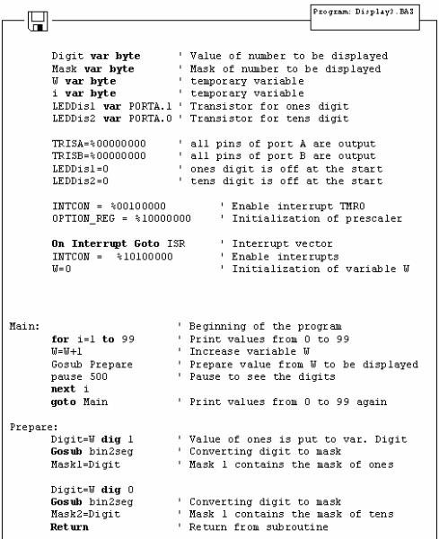
Problem with multiplexing occurs when displaying more than one digit is needed on two or more displays. It is necessary to put one mask on one digit quickly enough and activate it's transistor, then put the second mask and activate the second transistor (of course, if one of the transistors is in conducting mode, the other should not work because both digits will display the same value).
New program differs from the one above in converting 2-digits value to 2 masks, which are displayed in a way that human eye gets impression of simultaneous existence of both figures (this is the reason for calling it "multiplexing" - only one display actually emits in any given moment).
Let's say we need to display number 35. First, the number should be separated into tens and ones (in this case, digits 3 and 5) and their masks sent to port B. This separation can be done with instruction Dig. For example, Digit1= W dig 0 will extract ones digit from
variable W and store it into variable Digit1. If 0 is substituted with 1, tens digit will be extracted. Following the same logic, 2 extracts number of hundreds, 3 number of thousands, etc.
Basic for PIC Microcontrollers |
123 |
This part of program code prints value 35 on two seven-segment displays. The rest of the program is very similar to the last example, except for having one transition caused by displaying one digit after another. This transition can be spotted when LEDDisp1 is being turned off and LEDDisp2 turned on with a new mask. Lookup table is still the same and may be called as a subroutine when needed.
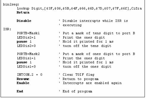
The multiplexing problem is solved for now, but the program doesn't have a sole purpose to print values on displays. It is commonly just a subroutine for displaying certain information. However, this kind of solution for printing data on display will make essence of the program much more complicated. This newly encountered problem may be solved by moving part of the program for refreshing the digits (part of the program code for handling the masks and controlling the transistors) to interrupt routine. The following program shows how to use interrupt for refreshing the display. Main program increases the value of variable W from 0 to 99 and that value is printed on displays. After reaching the value of 99, counter begins anew.
Basic for PIC Microcontrollers |
124 |
Basic for PIC Microcontrollers |
125 |
Interrupt initialized in this way will generate interrupt every time TMR0 timer changes state from 255 to 0. Every time interrupt takes place, interrupt routine will be executed so that human eye gets impression that both displays print values simultaneously. As can be seen from the program code, everything tied to displaying digits is moved to interrupt routine. However, part of the code for forming the masks to be displayed is in the special subroutine (Gosub Prepare) in order to make interrupt routine code as short as possible. Another reason for this kind of organization is also the need to create masks only when variable W is changed and not every time interrupt takes place.
In the course of main program, programmer doesn't have to take care of refreshing the display nor anything about displays whatsoever. It is only necessary to call subroutine "Preparation" every time value that will be displayed changes.
As 2-digit values don't satisfy most needs, the following step is adding two additional digits. Program for realization of 4 sevensegment displays is just an expansion of the program above. The main difference is in the part for separating values to ones, tens, hundreds and thousands.
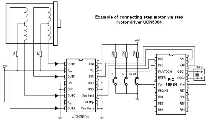
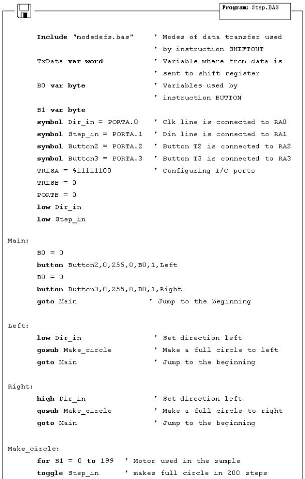
6.6 Step mo tor
Of all motors, step motor is the easiest to control. It's handling simplicity is really hard to deny - all there is to do is to bring the sequence of rectangle impulses to one input of step controller and direction information to another input. Direction information is very simple and comes down to "left" for logical one on that pin and "right" for logical zero. Motor control is also very simple - every impulse makes the motor operating for one step and if there is no impulse the motor won't start. Pause between impulses can be shorter or longer and it defines revolution rate. This rate cannot be infinite because the motor won't be able to "catch up" with all the impulses (documentation on specific motor should contain such information). The picture below represents the scheme for connecting the step motor to microcontroller and appropriate program code follows.
Basic for PIC Microcontrollers |
126 |
Basic for PIC Microcontrollers |
127 |
Basic for PIC Microcontrollers |
128 |
Basic for PIC Microcontrollers |
129 |
Chapter 7
SAMPLES WITH PIC16F877 MICROCONTROLLER
Introduction
7.1 Keyboard
7.2 Driver for seven-segment displays - MAX7912 7.3 LCD display
7.4 Serial EEPROM
7.5 RS-485
7.6 12-bit A/D converter LTC1290
7.7 12-bit D/A converter LTC1257
7.8 16-bit electrical current D/A converter AD421 7.9 Real time clock PCF8583
7.10 Digital thermometer DS1820
Introduction
This chapter gives detailed examples of connecting PIC16F877 microcontroller to peripheral components and appropriate programs written in BASIC. All of the examples contain electrical connection scheme and program with comments and clarifications. You have the permission to directly copy these examples from the book or download them from the web site http://www.mikroelektronika.co.yu/ .
7.1 Keyboard
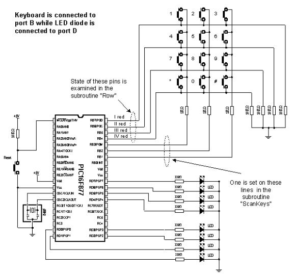
In more demanding applications that require greater number of buttons, it is possible to use buttons connected in matrix to keep microcontroller I/O lines free. The following sample includes scheme of connecting the keyboard and accompanying program which reads keyboard keys and prints the read value on LED diodes of port D.
Basic for PIC Microcontrollers |
130 |
The keys are connected into shared rows and columns. 10K resistors between input pins and the ground determine the state of input pins when the key is not pressed. It means that the logical zero is on input pins when the keys are not pressed. In order to avoid shortcircuits between two pressed keys, 1K resistor is added to each row.
Reading the keyboard is done by subroutine "ScanKeys". The keyboard is connected to port B, it's pins being designated as input for rows (RB7, RB6, RB5 and RB4) and output for columns (RB3, RB2 and RB1).