

Basic for PIC Microcontrollers (M. Nebojsa, 2001)
.PDFBasic for PIC Microcontrollers |
101 |
measure falls into 0-65536 microseconds range (with 4MHz frequency TMR01 increments by one microsecond). If prescaler is used that period can be prolonged, because prescaler divides the clock in a certain ratio (prescaler settings are made in T1CON register).
Before the main program, TMR1 should be enabled by setting the zero bit in T1CON register. Besides that, first bit of the register should be set to zero, thus defining the internal clock for TMR1.
Besides T1CON, other important registers for working with TMR1 include PIR1 and PIE1. The first contains overflow flag (zero bit) and the other is used to enable TMR1 interrupt (zero bit).
When TMR1 interrupt is enabled and its flag reset only thing left to do is to enable global interrupts (bit 7) and peripheral interrupts (bit 6) in the INTCON register.
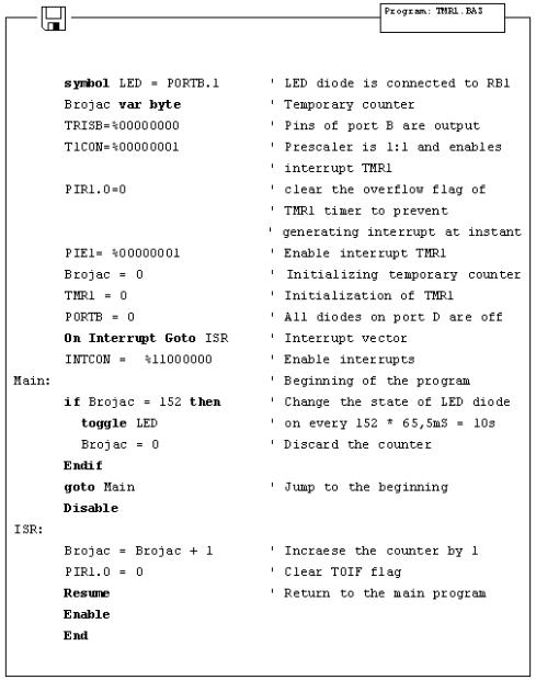
The following program illustrates use of TMR1 register for generating 10 seconds time period. Prescaler is set to 00 so there is no dividing the internal clock and overflow occurs every 65.536 ms. If variable "Brojac" is increased every time interrupt takes place, we can measure one minute period according to the variable "Brojac". If "Brojac" is set to 152, time will total 152*65.536 ms = 9.960 second.
Basic for PIC Microcontrollers |
102 |
5.5 Using the PWM subsystem
Microcontrollers of PIC16F87X series have one or two PWM outputs built-in (those in 40-pin casing have 2, while those in 28-pin casing have 1). PWM outputs are located on RC1 and RC2 pins in case of 40-pin microcontrollers and on RC2 pin in case of 28-pin microcontrollers. HPWM instruction greatly simplifies using the PWM. There are only 3 parameters to be set :
Basic for PIC Microcontrollers |
103 |
PWM Channel : defines which PWM channel is used; "1" defines channel on RC1 pin, while "2"
defines channel on RC2 pin.
Ratio_S_P : defines the ratio of on and off signals on pin. "0" defines continual
off state, whereas "255" defines continual on state. All values within these
limits define appropriate ratio of on and off signals on pin. (i.e. "127" gives
50% of 0V on output and 50% of 5V on output).
Frequency : defines PWM signal frequency. Top frequency for any oscillator is 32767Hz.
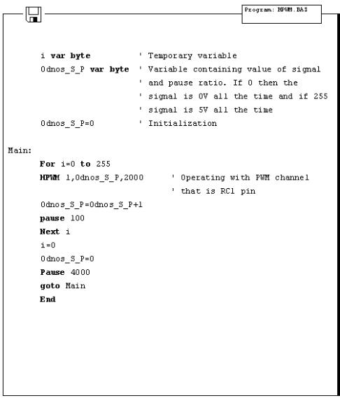
The following example demonstrates use of PWM for getting various light intensities on LED diode connected to RC1 pin (PWM channel 0). Parameter defining ratio of on and off signals is continually increased in the for-next loop and takes value from 0 to 255, resulting in continual intensifying of light on LED diode. After value of 255 has been reached, process begins anew.
Basic for PIC Microcontrollers |
104 |
5.6 Using the hardware UART subsystem (RS-232 communication)
Easiest way to transfer data between microcontroller and some other device (i.e. PC or other microcontroller) is the RS-232 communication. It is serial asynchronous 2-line (Tx for transmitting and Rx for receiving) data transfer for within 10m range.
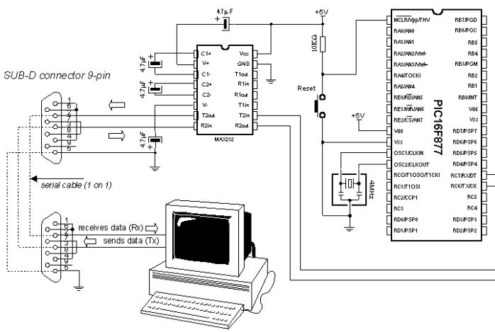
This example shows data transfer between the microcontroller and PC connected by RS-232 line interface (MAX232) which has role of adjusting signal levels on the microcontroller side (it converts RS-232 voltage levels +/- 10V to TTL levels 0-5V and vice versa). Microcontroller can achieve communication with serial RS-232 line via hardware UART (Universal Asynchronous Receiver Transmitter) which is the integral part of PIC16F87X microcontrollers.
Basic for PIC Microcontrollers |
105 |
UART contains special registers for receiving and transmitting data as well as BAUD RATE generator for determining data transfer rate.
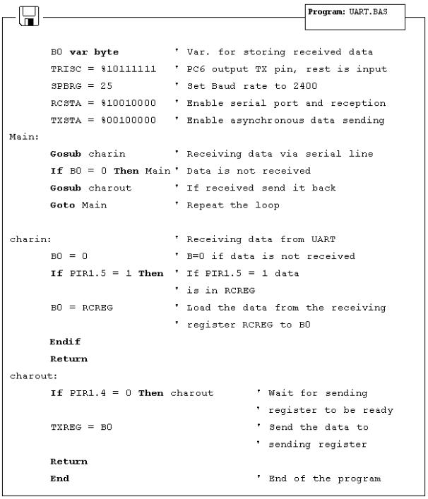
The program below illustrates use of hardware serial communication subsystem (serial communication can also be software based on any of 2 microcontroller pins). Data received from PC is stored into variable B0 and sent back to PC as confirmation of successful transfer. Thus, it is easy to check if communications works properly. Transfer format is 8N1 and transfer rate is 2400 baud.
In order to achieve communication, PC must have the communication software. One such program is part of the MicroCode studio. It can be accessed by clicking View and then Serial Communication Window. New window will appear on screen and can be used for adjusting transfer settings. First it is necessary to set transfer rate by clicking Baudrate on the left of the window (set it to 2400, because microcontroller is set to that rate). Communication port is selected by clicking one of the 4 available depending on port connected to a serial cable.
After making adjustments, clicking Connect starts the communication. Type your message and clickSend Message - message is sent to the microcontroller and back, where it is displayed on the screen.
Basic for PIC Microcontrollers |
106 |
Basic for PIC Microcontrollers |
107 |
Chapter 6
SAMPLES WITH PIC16F84 MICROCONTROLLER
Introduction
6.1 LED diode
6.2 Button
6.3 Generating sound
6.4 Potentiometer
6.5 Seven-segment displays
6.6 Step motor
6.7 Input shift register
6.8 Output shift register
6.9 Software serial communication
6.10 Building light control
Introduction
This chapter gives detailed examples of connecting PIC16F84 microcontroller to peripheral components and appropriate programs written in BASIC. All of the examples contain electrical connection scheme and program with comments and clarifications. You have the permission to directly copy these examples from the book or download them from the web site http://www.mikroelektronika.co.yu/ .
6.1 LED diode
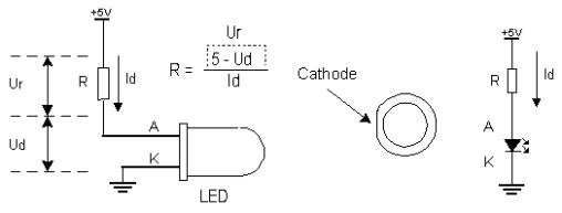
One of the most frequently used components in electronics is surely the LED diode (LED stands for Light Emitting Diode). Some of common LED diode features include : size, shape, color, working voltage (Diode voltage) Ud and electric current Id. LED diode can have round, rectangular or triangular shape, although manufacturers of these components can produce any needed shape by order. Size i.e. diameter of round LED diodes ranges from 3 to 12 mm, with 3 or 5 mm sizes most commonly used. Color of emitting light can be red, yellow, green, orange, blue, etc. Working voltage i.e. necessary for LED diode to emit light is 1.7V for red, 2.1V for green and 2.3 for orange color. This voltage can be higher depending on the manufacturer. Normal current Id through diode is 10 mA, while maximal current reaches 25 mA. High current consumption can present problem to devices with battery power supply, so in that case low current LED diode (Id ~ 1-2 mA) should be used. For LED diode to emit light with maximum capacity, it is necessary to connect it properly or it might get damaged.
Basic for PIC Microcontrollers |
108 |
The positive pole is connected to anode, while ground is connected to cathode. For matter of differentiating the two, cathode is marked by mark on casing and shorter pin. Diode will emit light only if current flows from anode to cathode; in the other case there will be no current. Resistor is added serial to LED diode, limiting the maximal current through diode and protecting it from damage. Resistor
value can be calculated from the equation on the picture above, where Ur represents voltage on resistor. For +5V power supply and 10 mA current resistor used should have value of 330¿.
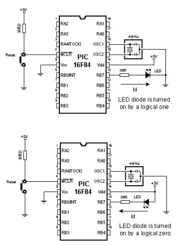
LED diode can be connected to microcontroller in two ways. One way is to have microcontroller "turning on" LED diode with logical one and the other way is with logical zero. The first way is not so frequent (which doesn't mean it doesn't have applications) because it requires the microcontroller to be diode current source. The second way works with higher current LED diodes.
Basic for PIC Microcontrollers |
109 |
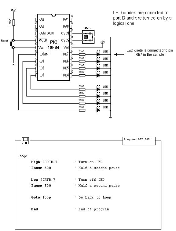
The following example uses instructions High, Low and Pause to turn on and off LED diode connected to seventh bit of port B every half second.
Basic for PIC Microcontrollers |
110 |