

Basic for PIC Microcontrollers (M. Nebojsa, 2001)
.PDFBasic for PIC Microcontrollers |
151 |
The New window Edit Project for the definition of the manufacturer. Choose “microEngeneering Labs”
The purpose oh this window is to set the microcontroller for which the program is written.
By clicking Change button, the new window for choosing the available microcontrollers appears. As an option, Editor only is to be left in the absence of any available Microchip’s tools (this option states the use of MPLAB as a shell for PIC Basic compiler).
Bu clicking Node Properties the window shown on the picture below appears. Choose "PM" version in the assembler selection. Clicking the OK returns us to the previous window.

Basic for PIC Microcontrollers |
152 |
The Add Node button is active now, and through it the name to the file with basic program is assigned. It is in our case, ‘probe.bas’. it is to take notice that the present action is only assigning name of the file into the project. Its actual creation is done in next step.
Window for naming the program in writing. Opening of the file is done in next step.
Basic for PIC Microcontrollers |
153 |
So far we defined microcontroller and the programming language. It still remains to open the file, write the code and register it under the name given in previous step. (proba.bas).
By clicking File-> New the window in which the basic program will be written appears.
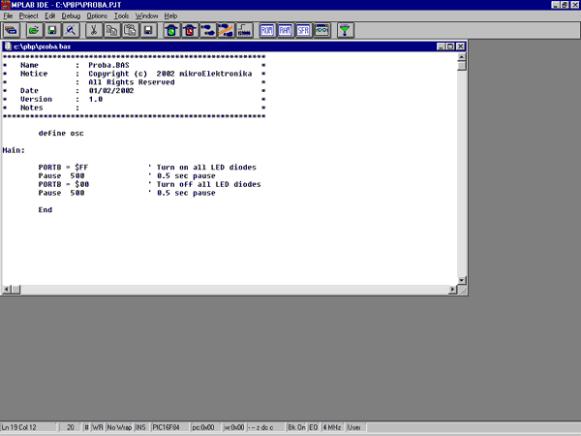
Before we start the program writing, file must be registered with the command File -> Save as, file name being obviously “proba.bas”. The code writing can start now. The program here serving as an example is a very simple one and its only function is to make the diode on a port B twinkle.
The window for writing Basic program
Upon finishing the code writing, the click on PROJECT-> Build All is performing the compilation of the program. Unless there have been some errors, the obtained file is C:/PBP/probe.hex readable into the microcontroller.

Basic for PIC Microcontrollers |
154 |
A.3 Toolbar
Since MPLAB is composed of several separate parts, each of them possesses its own toolbar. However, there exists a toolbar being a sort of a combination of all the others, which may be considered as a common one. This toolbar is sufficient for our needs so it will be the explained in details. On the picture bellow this toolbar is given with the brief explanations of the icons. Out of the limited format of this book, the basic toolbar is displayed as the free one and in a standard position is always bellow the menu, displaced horizontally along the entire screen.
If, for whatever reason, currently used toolbar does not respond, upon clicking this icon the next toolbar becomes available. The change goes into circle so that upon the 4th click, the same toolbar is obtained again.
If the current toolbar for some reason does not respond to a click on this icon, the next one appears. Changeover is repeated so that on the fourth click we will get the same toolbar again.
Icon for opening a project. Project opened in this way contains all screen adjustments and adjustment

Basic for PIC Microcontrollers |
155 |
Icon for saving a project. Saved project will keep all window adjustments and all parameter adjustmen When we read in a program again, everything will return to the screen as when the project was closed
Searching for a part of the program, or words is operation we need when searching through bigger ass or other programs. By using it, we can find quickly a part of the program, label, macro, etc.
Cutting a part of the text out. This one and the following three icons are standard in all programs that with processing textual files. Since each program is actually a common text file, those operations are u
Copying a part of the text. There is a difference between this one and the previous icon. With cut oper when you cut a part of the text out, it disappears from the screen (and from a program) and is copied afterwards. But with copy operation, text is copied but not cut out, and it remains on the screen.
When a part of the text is copied, it is moved into a part of the memory which serves for transferring d Windows operational system. Later, by clicking on this icon it can be 'pasted' in the text where the cur
Saving a program (assembler file).
Start program execution in full speed. It is recognized by appearance of a yellow status line. With this program execution, simulator executes a program in full speed until it is interrupted by clicking on the traffic light icon.
Stop program execution in full speed. After clicking on this icon, status line becomes gray again, and p execution can continue step by step.
Step by step program execution. By clicking on this icon, we begin executing an instruction from the n program line in relation to the current one.
Skip requirements. Since simulator is still a software simulation of real work, it is possible to simply sk some program requirements. This is especially handy with instructions which are waiting for some requirement following which program can proceed further. That part of the program which follows a requirement is the part that 's interesting to a programmer.
Resetting a microcontroller. By clicking on this icon, program counter is positioned at the beginning of program and simulation can start.
By clicking on this icon we get a window with a program, but this time as program memory where we which instruction is found at which address.
With the help of this icon we get a window with the contents of RAM memory of a microcontroller.
By clicking on this icon, window with SFR register appears. Since SFR registers are used in every progr is recommended that in simulator this window is always active.
If a program contains variables whose values we need to keep track of (ex. counter), a window needs added for each of them, which is done by using this icon.
When certain errors in a program are noticed during simulation process, program has to be corrected. simulator uses HEX file as its input, so we need to translate a program again so that all changes would transferred to a simulator. By clicking on this icon, entire project is translated again, and we get the n version of HEX file for the simulator.
Basic for PIC Microcontrollers |
156 |
Appendix B
MicroCODE STUDIO
Introduction
B.1 Installation of the PIC Basic Pro compiler
B.2 Installation of a MicroCODE studio
B.3 Connecting MicroCODE Studio and PBP compiler
B.4 Connecting MicroCODE Studio and the programmer
B.5 Code writing and compilation in MicroCODE studio
Introduction
Although the code writing can be done with the simplest editor and compiled in command line (those who had programmed in DOS probably remember well those acrobatics) using special “editors” appropriate for programming language is far better.
Such specialized editors are called “Integrated Development Environments” - IDE. Using them makes code writing easier as the programmer is able to supervise which variables, labels or similar program elements have already been used. At the same time, they make command words bold and even write them in another color rendering thereby program more intelligible. The option for automatic call up of the programmer is also available together with many other facilities. Simply put, having those facilities without using them is like climbing on foot to the 13th floor of a building with elevator.
B.1 Installation of the PIC Basic Pro compiler
The first thing to be done is to create a new directory into which the compiler will stored. Let it be the directory C:/PBP. Then follows the copying of data file PBP240.EXE into that directory and its unpacking (compiler enters in the form of unpacking archive)? by double-clicking it. Unless the compiler is unpacked it is enough to copy it into the desired directory.
B.2 Installation of a MicroCODE studio
Installation of the editor starts by double-clicking on MCSTUDIO. Afterwards, the standard setup process is started where the computer location for the editor’s installationcan be chosen. The setup process starts with the usual warning to close all other active windows. By clicking on button Next, the setup continues.

Basic for PIC Microcontrollers |
157 |
The first window after the installation starts. It is necessary to click on button Next
Next question is whether you accept the license and copyright rules or not. By accepting these rules by clicking on the Yes button, the installation goes forward. The next image corresponds to that phase of the installation.

Basic for PIC Microcontrollers |
158 |
The directory for editor location is the next question. In case of failed statement of the directory, the installation is to be effectuated in C:\ProgramFiles\Mecaniqe.
The choice of an installation directory. The best choice is to leave the option by default. It is necessary to click on OK button in order to proceed

Basic for PIC Microcontrollers |
159 |
The name and address of directory is without any special meaning for further programming. The real issue is the available memory space on the hard disk or on the need for keeping all items associated with a single program in the same directory.
The next question refers to the name of programming group. The name already offered corresponds to the program name so it should be left as such.
The program group is to be named MicroCodeStudio. Clicking on Next, the installation goes on
Finally, the window appears confirming the successfully performed installation.
Basic for PIC Microcontrollers |
160 |
B.3 Connecting MicroCODE Studio and PBP compiler
Clicking on Start-Programs-MicroCode Studio starts up the just installed MicroCode Studio and the window from the picture bellow will appear.