

Basic for PIC Microcontrollers (M. Nebojsa, 2001)
.PDFBasic for PIC Microcontrollers |
111 |
6.2 Button
Button is a mechanical component which connects or disconnects two points A and B over its contacts. By function, button contacts can be normally open or normally closed.
Pressing the button with normally open contact connects t he points A and B, while pressing the button with normally closed contact disconnects A and B.
Buttons can be connected to the microcontroller in one of two ways:
In the first case, button is connected in a way that logical one (+5V) remains on microcontroller input pin while button is not pressed. Resistor between a button and power voltage has role of holding the input pin in defined state when the button is not pressed (in this case a logical one). This is necessary as a protection from glitch on input pin that might cause misinterpretation of program, i.e. as if button is pressed when it is not.
When the button is pressed, input pin is short circuited to the ground (0V) which indicates change on input pin. Voltage has dropped

Basic for PIC Microcontrollers |
112 |
from 5V to 0V. This change is interpreted by program as if button was pressed and part of program code tied to a button (for example turn on LED diode) is then executed. This way of defining pin states is called defining with "pull-up" resistors, associating that the line is held up on the logical one level.
In the other case, button is connected in a way that logical zero remains on input pin. Now, resistor is between input pin and a logical zero, meaning that pressing the button brings logical one to input pin. Voltage goes up from 0V to +5V. Microcontroller program should recognize change on input pin and execute the specific part of program code. This way of defining pin states is called defin ing with "pull -down" resistors, associating that the line is held down on the logical zero level.
Common way to connect the button is with pull-up resistors, meaning that pressing the button changes pin state from logical one to logical zero. Following picture displays four button connected to the microcontroller using the pull -up resistors.

Basic for PIC Microcontrollers |
113 |
Problem that occurs when working with buttons is contact debounce in the moment when button is pressed. Debounce is consequence of the contact and heavily depends on the very button.
One of the ways to solve the contact debounce problem is given in the following part of program code :
Pressing the Button0 causes the program to jump to address Wait0 where it remains in the loop until the button is released (this achieves that single button push is just once handled in program). When Button0 is released program continues executing instructions (in this case variable W is increased by one). Pressing Button1 causes the same effect, except that variable W is decreased by one.
Problem might arise if an interrupt or some other source slows down the program execution, so that program finds itself on Wait0 or
Basic for PIC Microcontrollers |
114 |
Wait1 lines after the button is released. This might cause program blocking until button is pressed again.
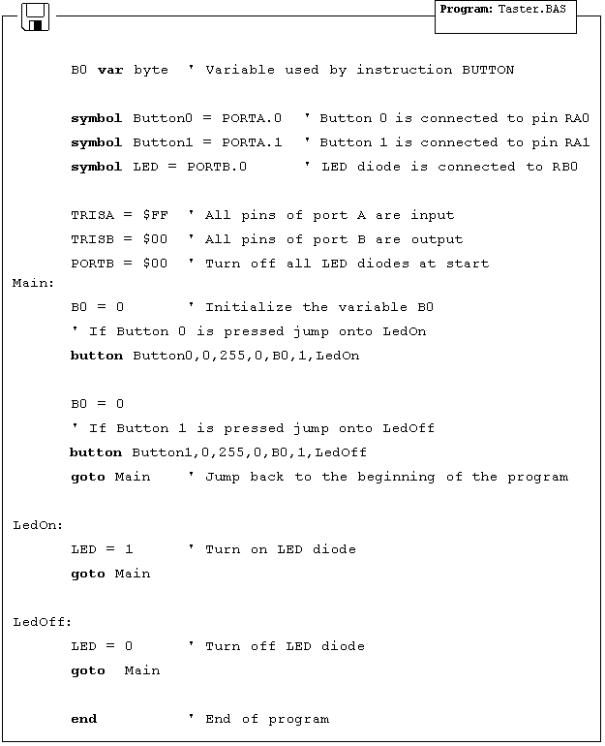
In the following program for reading the button states, BASIC instruction Button is used which eliminates the contact debounce.
The program reads buttons T0 and T1 which are connected to the pins RA0 and RA1, respectively. Pressing the button 0 executes part of program code which turns on LED diode on pin RB0. Pressing the button 1 executes part of program code which turns off LED diode on the same pin. The mentioned instruction is among the most complex instructions of BASIC program language. Besides few arguments that should be defined, instruction has an argument for setting the delay time between recognition of two different button pressures (the third argument). Its setting depends on the purpose of the button as well as mechanical properties of the button. Still, it came clear over time that maximal value of last argument represents the best solution for most applications, because of great disproportion in human reaction and microcontroller speed.
Basic for PIC Microcontrollers |
115 |
6.3 Generating sound

Basic for PIC Microcontrollers |
116 |
Sometimes it is necessary to provide sound signalization on device, besides the visual one (LED diodes). The following example shows one way to generate sound signal using the mini speaker and BASIC instruction Sound.
Buttons are connected to pins RA0, RA1 and RA2. Pressing any of these executes part of the code for generating impulse sequence on RA3 pin, which can be heard as one monotonous sound or a melody on mini speaker. Consecutive execution of instruction Sound with different parameters allows composing various melodies.
In the following program, pressing the button T0 generates one monotonous sound on a mini speaker, while pressing the buttons T1 and T2 executes sequences of Sound instructions which can be heard as two different melodies on a mini speaker.

Basic for PIC Microcontrollers |
117 |
6.4 Potentiometer

Basic for PIC Microcontrollers |
118 |
In order to measure and display analog values, besides the microcontroller, it is necessary to have an AD converter. This can be an expensive solution if some less precise measuring is required, for example potentiometer voltage. For this reason PIC BASIC features the POT instruction for using the microcontroller without AD converter.
RC pair which consists of potentiometer (typical resistance in 5-50k range) and a 100nF capacitor is connected to RA0 pin. Reading the potentiometer is based upon measuring the time period between capacitor discharging and charging. Measuring scale ranges from 0 to 255 as if 8-bit AD converter was used.
The following program reads potentiometer value in 0-255 range and displays it on LED diodes connected to the port B.

Basic for PIC Microcontrollers |
119 |
6.5 Seven-segment displays
Most common form of communication between the microcontroller system and a man is, of course, the visual communication. The simplest form is the LED diode, while seven-segment digits represent more advanced form of visual communication. The name comes from the seven diodes (there is an eighth diode for a dot) arranged to form decimal digits from 0 to 9. Appearance of a seven-segment digit is given on a picture below.

Basic for PIC Microcontrollers |
120 |
Asseven-segment digits have better temperature features as well as visibility than LCD displays, they are very common in industrial applications. Their use satisfies all criteria including the financial one. Simple application would be displaying value read from a certain sensor.
One of the ways to connect seven-segment display to the microcontroller is given on a picture above. System is connected to use seven-segment digits with common cathode. This means that segments emit light when logical one is brought to them, and that output
of all segments must be a transistor connected to common cathode, as shown on the picture. If transistor is in conducting mode any segment with logical one will emit light, and if not no segment will emit light, regardless of its pin state.
If we use the scheme from the picture above, one of the ways to realize the display in BASIC could be the following program code :