

B.Crowell - Optics, Vol
.5.pdfExercise 5B: Single-slit diffraction
Equipment: rulers
computer spreadsheet or computer program for adding sine waves
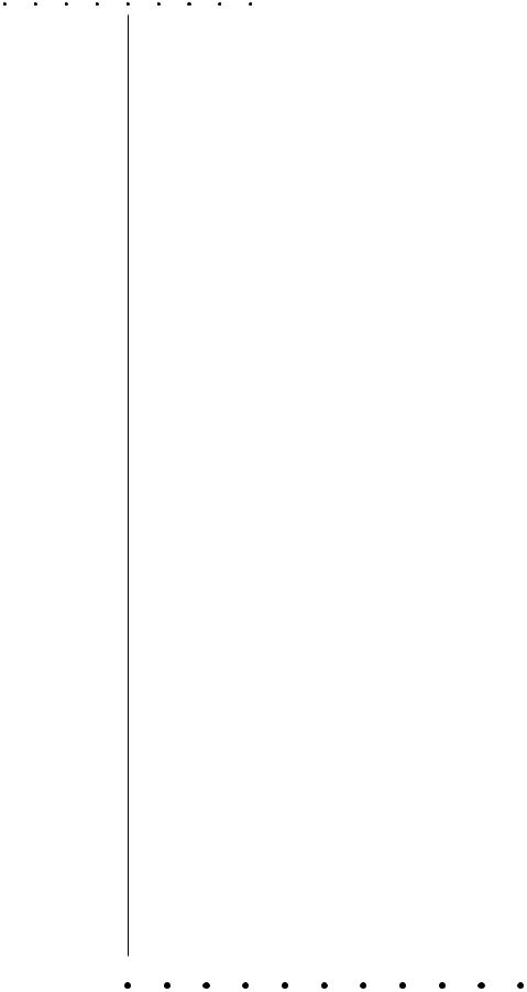
The following page is a diagram of a single slit and a screen onto which its diffraction pattern is projected. The class will make a numerical prediction of the intensity of the pattern at the different points on the screen. Each group will be responsible for calculating the intensity at one of the points. (Either 11 groups or six will work nicely -- in the latter case, only points a, c, e, g, i, and k are used.) The idea is to break up the wavefront in the mouth of the slit into nine parts, each of which is assumed to radiate semicircular ripples as in Huygens’ principle. The wavelength of the wave is 1 cm, and we assume for simplicity that each set of ripples has an amplitude of 1 unit when it reaches the screen.
1. For simplicity, let’s imagine that we were only to use two sets of ripples rather than nine. You could measure the distance from each of the two points inside the slit to your point on the screen. Suppose the distances were both 25.0 cm. What would be the amplitude of the superimposed waves at this point on the screen?
Suppose one distance was 24.0 cm and the other was 25.0 cm. What would happen?
What if one was 24.0 cm and the other was 26.0 cm?
What if one was 24.5 cm and the other was 25.0 cm?
In general, what combinations of distances will lead to completely destructive and completely constructive interference?
Can you estimate the answer in the case where the distances are 24.7 and 25.0 cm?
2. Although it is possible to calculate mathematically the amplitude of the sine wave that results from superimposing two sine waves with an arbitrary phase difference between them, the algebra is rather laborious, and it become even more tedious when we have more than two waves to superimpose. Instead, one can simply use a computer spreadsheet or some other computer program to add up the sine waves numerically at a series of points covering one complete cycle. This is what we will actually do. You just need to enter the relevant data into the computer, then examine the results and pick off the amplitude from the resulting list of numbers.
3. Measure all nine distances to your group’s point on the screen, and write them on the board - that way everyone can see everyone else’s data, and the class can try to make sense of why the results came out the way they did. Determine the amplitude of the combined wave, and write it on the board as well.
4. Why do you think the intensity at the center came out the way it did? Would it have mattered if we had used 900 sets of ripples rather than 9?
5. Looking at the raw data for the point that had the least intensity, can you see why it came out that way?
6. What do you notice about the width of the central maximum compared to the width of the first side maximum? How is this different from double-slit interference? Compare with figure (b) in section 5.7.
7. Although the pattern goes up and down, the general trend is that the farther away we get from the center, the weaker it gets. Why does it make sense that the intensity at some random angle far from the center would tend to be small?
8. Single-slit diffraction can actually be calculated using equations in closed form rather than doing it numerically, and one result is that the intensity of the second maximum is always smaller than the intensity of the central maximum by a factor of 4/9π2. Note that the intensity (in units of watts per unit area) is proportional to the square of the wave’s amplitude. Compare our results with the exact result.
81
|
|
|
|
|
|
|
|
|
|
|
|
|
|
|
|
a |
b |
c |
d |
e |
f |
g |
h |
i |
j |
k |
|
|
|
|
|
|
|
|
|
|
|
|
|
|
|
82
83
84
Solutions to Selected Problems
Chapter 3
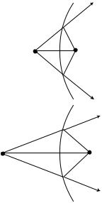
2. See the ray diagrams below. Increasing di increases do, so the equation 1/f = +1/di + 1/do must have opposite signs on the right. Physically, we can have a virtual image with di=∞, but not with do=∞, so the positive sign has to be the one in front of do, giving 1/f = –1/di + 1/do.
(a)
1.25 rad=72°. This is a decent approximation.
(c) With the 28-mm lens, which is closer to the film, the entire field of view we had with the 50-mm lens is now confined to a small part of the film. Using our small-angle approximation θ=w/f, the amount of light contained within the same angular width θ is now striking a piece of the film whose linear dimensions are smaller by the ratio 28/50. Area depends on the square of the linear dimensions, so all other things being equal, the film would now be overexposed by a factor of (50/28)2=3.2. To compensate, we need to shorten the exposure by a factor of 3.2.
(b)
Problem 2.
Chapter 4
13. Since do is much greater than di, the lens-film distance di is essentially the same as f. (a) Splitting the triangle inside the camera into two right triangles, straightforward trigonometry gives
θ = 2 arctan(w/2f)
for the field of view. This comes out to be 39° and 64° for the two lenses. (b) For small angles, the tangent is approximately the same as the angle itself, provided we measure everything in radians. The equation above then simplifies to
θ = w/f
The results for the two lenses are .70 rad=40°, and
Solutions to Selected Problems |
85 |
86
Glossary
Absorption. What happens when light hits matter and gives up some of its energy.
Angular magnification. The factor by which an image’s apparent angular size is increased (or decreased). Cf. magnification.
Coherent. A light wave whose parts are all in phase with each other.
Concave. Describes a surface that is hollowed out like a cave.
Convex. Describes a surface that bulges outward.
Diffraction. The behavior of a wave when it encounters an obstacle or a nonuniformity in its medium; in general, diffraction causes a wave to bend around obstacles and make patterns of strong and weak waves radiating out beyond the obstacle.
Diffuse reflection. Reflection from a rough surface, in which a single ray of light is divided up into many weaker reflected rays going in many directions.
Focal length. A property of a lens or mirror, equal to the distance from the lens or mirror to the image it forms of an object that is infinitely far away.
Image. A place where an object appears to be, because the rays diffusely reflected from any given point on the object have been bent so that they come back together and then spread out again from the image point, or spread apart as if they had originated from the image.
Index of refraction. An optical property of matter; the speed of light in a vacuum divided by the speed of light in the substance in question.
Magnification. The factor by which an image’s linear size is increased (or decreased). Cf. angular magnification.
Real image. A place where an object appears to be, because the rays diffusely reflected from any given point on the object have been bent so that they come back together and then spread out again from the new point. Cf. virtual image.
Reflection. What happens when light hits matter and bounces off, retaining at least some of its energy.
Refraction. The change in direction that occurs when a wave encounters the interface between two media.
Specular reflection. Reflection from a smooth surface, in which the light ray leaves at the same angle at which it came in.
Virtual image. Like a real image, but the rays don’t actually cross again; they only appear to have come from the point on the image. Cf. real image.
87
88
A
aberration 41 absorption 15
angular magnification 29
B
Bohr
Niels 62 brightness of light 16 Bush, George 45
C
color 51 concave
defined 31 convex
defined 31
D
diffraction defined 60 double-slit 64 fringe 61 scaling of 61 single-slit 69
diffraction grating 69 diffuse reflection 15 diopter 36
double-slit diffraction 64
E
Empedocles of Acragas 12 evolution 45
eye
evolution of 45 human 46
F
Fermat’s principle 22 flatworm 46
focal angle 34 focal length 35 negative 43
fringe diffraction 61
G
Galileo 13
Index
H
Hertz, Heinrich
Heinrich 63
Huygens’ principle 63
I
images
formed by curved mirrors 27 formed by plane mirrors 26 location of 34
of images 29 real 28 virtual 26
inbending defined 27
incoherent light 61 index of refraction
defined 48
related to speed of light 49 Io 14
J
Jupiter 14
L
least time principle of
for reflection 22 for refraction 54
lensmaker’s equation 54 light
absorption of 15 brightness of 16 particle model of 17 ray model of 17 speed of 13
wave model of 17
M
magnification angular 29
by an inbending mirror 27 negative 43
Maxwell, James Clerk 64 mirror
inbending 34 mollusc 46 Moses 45
Index 89
N
nautilus 46
Newton, Isaac 29, 63
O
optical density. See index of refraction: defined orrespondence principle 62
outbending defined 31
P
particle model of light 17, 63 Pythagoras 12
R
ray diagrams 18
ray model of light 17, 63 reflection
diffuse 15 specular 20
refraction
and color 51 defined 46
repetition of diffracting objects 68 retina 28
reversibility 20 Roemer 14
S
single-slit diffraction 69
Snell’s law 48 derivation of 50
mechanical model of 49 Squid 46
T
telescope 70 time reversal 20
total internal reflection 51
V
vision 12
W
wave model of light 17, 63 Wigner, Eugene 33
Y
Young, Thomas 63
90 Index