

B.Crowell - Optics, Vol
.5.pdfSummary
Selected Vocabulary |
|
real image .......................... |
a place where an object appears to be, because the rays diffusely reflected |
|
from any given point on the object have been bent so that they come back |
|
together and then spread out again from the new point |
virtual image ..................... |
like a real image, but the rays don’t actually cross again; they only appear |
|
to have come from the point on the image |
inbending .......................... |
describes an optical device that brings light rays closer to the optical axis |
outbending ........................ |
bends light rays farther from the optical axis |
magnification .................... |
the factor by which an image’s linear size is increased (or decreased) |
angular magnification ........ |
the factor by which an image’s apparent angular size is increased (or |
|
decreased) |
Vocabulary Used in Other Books |
|
concave ............................. |
describes a surface that is hollowed out like a cave |
convex ............................... |
describes a surface that bulges outward |
Notation |
|
M ...................................... |
the magnification of an image |
Ma ................................................................ |
the angular magnification of an image |
Summary
A large class of optical devices, including lenses and flat and curved mirrors, operates by bending light rays to form an image. A real image is one for which the rays actually cross at each point of the image. A virtual image, such as the one formed behind a flat mirror, is one for which the rays only appear to have crossed at a point on the image. A real image can be projected onto a screen; a virtual one cannot.
Mirrors and lenses will generally make an image that is either smaller than or larger than the original object. The scaling factor is called the magnification. In many situations, the angular magnification is more important than the actual magnification.
Homework Problems |
31 |

Homework Problems
1 . A man is walking at 1.0 m/s directly towards a flat mirror. At what speed is his separation from his image reducing?
2. If a mirror on a wall is only big enough for you to see yourself from your head down to your waist, can you see your entire body by backing up? Test this experimentally and come up with an explanation for your observations. Note that it is easy to confuse yourself if the mirror is even a tiny bit off of vertical; check whether you are able to see more of yourself both above and below.
3. In this chapter we’ve only done examples of mirrors with hollowed-out shapes (called concave mirrors). Now draw a ray diagram for a curved mirror that has a bulging outward shape (called a convex mirror). (a) How does the image’s distance from the mirror compare with the actual object’s distance from the mirror? From this comparison, determine whether the magnification is greater than or less than one. (b) Is the image real or virtual? Could this mirror ever make the other type of image?
4. As discussed in question 3, there are two types of curved mirrors, concave and convex. Make a list of all the possible combinations of types of images (virtual or real) with types of mirrors (concave and convex). (Not all of the four combinations are physically possible.) Now for each one, use ray diagrams to determine whether increasing the distance of the object from the mirror leads to an increase or a decrease in the distance of the image from the mirror.
5. If the user of an astronomical telescope moves her head closer to or farther away from the image she is looking at, does the magnification change? Does the angular magnification change? Explain.
32
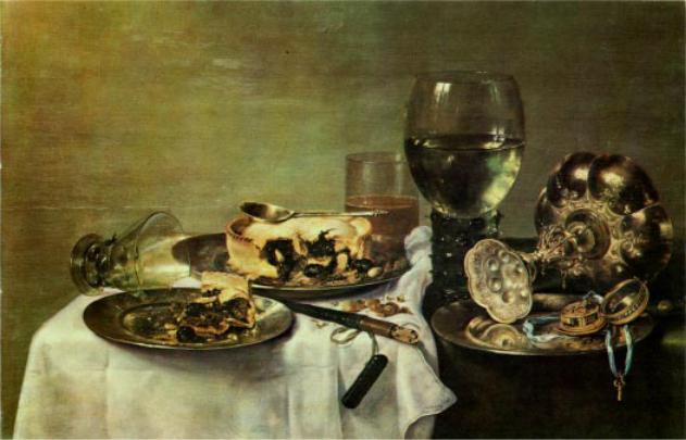
Breakfast Table, by Willem Claesz. de Heda, 17th century. A variety of images occur in the painting, some distorted, as a result of both reflection and refraction (ch. 4).
3 Images by Reflection, Part II
It sounds a bit odd when a scientist refers to a theory as “beautiful,” but to those in the know it makes perfect sense. One mark of a beautiful theory is that it surprises us by being simple. The mathematical theory of lenses and curved mirrors gives us just such a surprise. We expect the subject to be complex because there are so many cases: an inbending mirror forming a real image, an outbending lens that makes a virtual image, and so on for a total of six possibilities. If we want to predict the location of the images in all these situations, we might expect to need six different equations, and six more for predicting magnifications. Instead, it turns out that we can use just one equation for the location of the image and one equation for its magnification, and these two equations work in all the different cases with no changes except for plus and minus signs. This is the kind of thing the physicist Eugene Wigner referred to as “the unreasonable effectiveness of mathematics.” Sometimes we can find a deeper reason for this kind of unexpected simplicity, but sometimes it almost seems as if God went out of Her way to make the secrets of universe susceptible to attack by the human thought-tool called math.
33
3.1 A Real Image Formed by an Inbending Mirror
Location of the image
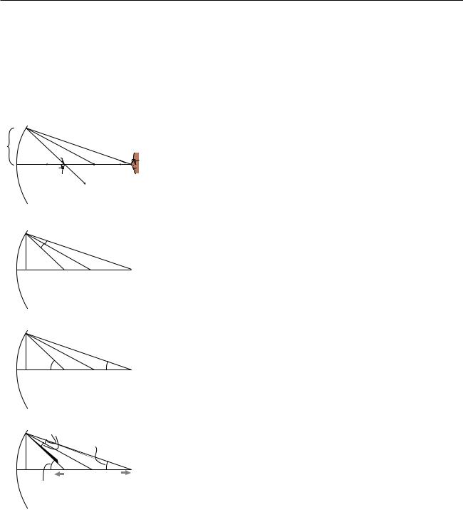
We will now derive the equation for the location of a real image formed by an inbending mirror. We assume for simplicity that the mirror is spherical, but actually this isn’t a restrictive assumption, because any shallow, symmetric curve can be approximated by a sphere. The shape of the mirror can be specified by giving the location of its center, C. A deeply curved mirror is a sphere with a small radius, so C is close to it, while a weakly curved mirror has C farther away. Given the point O where the object is, we wish to find the point I where the image will be formed.
(a)To locate an image, we need to track a minimum of two rays coming
1 |
|
|
from the same point. Since we have proved in the previous chapter that this |
|
|
type of image is not distorted, we can use an on-axis point, O, on the |
|
|
I |
C |
|
|
|
||
|
|
O |
object, as in figure (a). The results we derive will also hold for off-axis |
|
|
|
points, since otherwise the image would have to be distorted, which we |
|
|
|
know is not true. We let one of the rays be the one that is emitted along the |
|
|
|
axis; this ray is especially easy to trace, because it bounces straight back |
|
|
|
along the axis again. As our second ray, we choose one that strikes the |
|
|
|
mirror at a distance of 1 from the axis. “One what?” asks the astute reader. |
(b)The answer is that it doesn’t really matter. When a mirror has shallow curvature, all the reflected rays hit the same point, so 1 could be expressed in any units you like. It could, for instance, be 1 cm, unless your mirror is smaller than 1 cm!
The only way to find out anything mathematical about the rays is to use the sole mathematical fact we possess concerning specular reflection: the incicent and reflected rays form equal angles with respect to the normal,
(c)which is shown as a dashed line. Therefore the two angles shown in figure
(b) are the same, and skipping some straightforward geometry, this leads to θi θo the visually reasonable result that the two angles in figure (c) are related as
follows:
θi+θo = constant
Suppose, for example, that we move O farther from the mirror. The top
get bigger gets |
(d) |
angle in figure (b) is increased, so the bottom angle must increase by the |
|
|
|||
|
same amount, causing the image point, I, to move closer to the mirror. In |
||
|
smaller |
||
|
terms of the angles shown in figure (c), the more distant object has resulted |
||
|
|
|
|
|
|
|
in a smaller angle θo, while the closer image corresponds to a larger θi; One |
|
I |
O |
angle increases by the same amount that the other decreases, so their sum |
gets |
remains constant. These changes are summarized in figure (d). |
||
bigger |
moves |
moves |
The sum θi+θo is a constant. What does this constant represent? Geo- |
|
closer |
away |
|
metrically, we interpret it as double the angle made by the dashed radius line. Optically, it is a measure of the strength of the mirror, i.e., how strongly the mirror focuses light, and so we call it the focal angle, θf,
θi+θo = θf
Suppose, for example, that we wish to use a quick and dirty optical test to determine how strong a particular mirror is. We can lay it on the floor as shown in figure (e), and use it to make an image of a lamp mounted on the ceiling overhead, which we assume is very far away compared to the radius of curvature of the mirror, so that the mirror intercepts only a very narrow
34 |
Chapter 3 Images by Reflection, Part II |
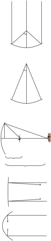
θf
(e) The geometric interpretation of the focal angle.
θ
(f) An alternative test for finding the focal angle. The mirror is the same as in figure (d),
di
do
(g) The object and image distances.
(h) The top mirror has a shallower curvature, a longer focal length, and a smaller focal angle. It reflects rays at angles not much different from those that would be produced with a flat mirror.
cone of rays from the lamp. This cone is so narrow that its rays are nearly parallel, and θo is nearly zero. The real image can be observed on a piece of paper. By moving the paper nearer and farther, we can bring the image into focus, at which point we know the paper is located at the image point. Since θo≈0, we have θi≈θf, and we can then determine this mirror’s focal angle either by measuring θi directly with a protractor, or indirectly via trigonometry. A strong mirror will bring the rays to a focal point close to
the mirror, and these rays will form a blunt-angled cone with a large θi and θf.
Example: An alternative optical test
Question: Figure (f) shows an alternative optical test. Rather than placing the object at infinity as in figure (e), we adjust it so that the image is right on top of the object. Points O and I coincide, and the rays are reflected right back on top of themselves. If we measure the angle θ shown in figure (f), how can we find the focal angle?
Solution: The object and image angles are the same; the angle labeled θ in the figure equals both of them. We therefore have θi+θo = 2θ= θf. Comparing figures (e) and (f), it is indeed plausible that the angles are related by a factor of two.
At this point, we could consider our work to be done. Typically, we know the strength of the mirror, and we want to find the image location for a given object location. Given the mirror’s focal angle and the object location, we can determine θo by trigonometry, subtract to find θi=θf–θo, and then do more trig to find the image location.
There is, however, a shortcut that can save us from doing so much work. Figure (c) shows two right triangles whose legs of length 1 coincide and whose acute angles are θo and θi. These can be related by trigonometry to the object and image distances shown in figure (g):
tan θo = 1/do |
tan θi = 1/di |
Ever since chapter 2, we’ve been assuming small angles. For small angles, we can use the small-angle approximation tan x≈x (for x in radians), giving simply
θo = 1/do |
θi = 1/di . |
We likewise define a distance called the focal length, f according to θf = 1/f. In figure (e), f is the distance from the mirror to the focal point. We can now reexpress the equation relating the object and image positions as
1 |
= |
1 |
+ |
1 |
. |
|
|
||||
f |
|
d i |
d o |
||
Figure (h) summarizes the interpretation of the focal length and focal angle.
Which form is better, θf = θi+θo or 1/f = 1/di+1/do? The angular form has in its favor its simplicity and its straightforward visual interpretation, but there are two reasons why we might prefer the second version. First, the numerical values of the angles depend on what we mean by “one unit” for the distance shown as 1 in figure (a). Second, it is usually easier to measure distances rather than angles, so the distance form is more convenient for number crunching. Neither form is superior overall, and we will often need to use both to solve any given problem. (I would like to thank Fouad Ajami
Section 3.1 A Real Image Formed by an Inbending Mirror |
35 |
for pointing out the pedagogical advantages of using both equations side by side.)
Example: A searchlight
Suppose we need to create a parallel beam of light, as in a searchlight. Where should we place the lightbulb? A parallel beam has zero angle between its rays, so θi=0. To place the lightbulb correctly, however, we need to know a distance, not an angle: the distance do between the bulb and the mirror. The problem involves a mixture of distances and angles, so we need to get everything in terms of on or the other in order to solve it. Since the goal is to find a distance, let’s figure out the image distance corresponding to the given angle θi=0. These are related by di=1/θi, so we have di=∞. (Yes, dividing by zero gives infinity. Don’t be afraid of infinity. Infinity is a useful problemsolving device.) Solving the distance equation for do, we have
d |
o |
= |
(1/f – 1/d ) –1 |
|
= |
i |
|
|
|
(1/f – 0) –1 |
|
|
|
= |
(1/f ) –1 |
|
|
= |
f |
The bulb has to be placed at a distance from the mirror equal to its focal point.
Example: Diopters
An equation like di=1/θi really doesn’t make sense in terms of units. Angles are unitless, since radians aren’t really units, so the right-hand side is unitless. We can’t have a left-hand side with units of distance if the right-hand side of the same equation is unitless. This is an artifact of our cavalier statement that our conical bundles of rays spread out to a distance of 1 from the axis where they strike the mirror, without specifying the units used to measure this 1. In real life, optometrists define the thing we’re calling θi=1/di as the “dioptric strength” of a lens or mirror, and measure it in units of inverse meters (m –1), also known as diopters (1 D = 1 m –1).
Magnification
We have already discussed in the previous chapter how to find the magnification of a virtual image made by a curved mirror. The result is the same for a real image, and we omit the proof, which is very similar. In our new notation, the result is M=di/do. An numerical example is given in the following section.
36 |
Chapter 3 Images by Reflection, Part II |

di
unphysical — negative do can be interpreted as placing the object on the other side of the mirror, but then no image is produced
real image
do = f
di = f
do
virtual image — negative di can be interpreted as an image on the far side of the mirror
3.2 Other Cases With Curved Mirrors
The equation d = 1/f – 1/d o |
– 1 |
can easily produce a negative result, |
|
i |
|
but we have been thinking of di as a distance, and distances can’t be negative. A similar problem occurs with θi=θf–θo for θo>θf. What’s going on here?
The interpretation of the angular equation is straightforward. As we bring the object closer and closer to the image, θo gets bigger and bigger, and eventually we reach a point where θo=θf and θi=0. This large object angle represents a bundle of rays forming a cone that is very broad, so broad that the mirror can no longer bend them back so that they reconverge on the axis. The image angle θi=0 represents an outgoing bundle of rays that are parallel. The outgoing rays never cross, so this is not a real image, unless we want to be charitable and say that the rays cross at infinity. If we go on bringing the object even closer, we get a virtual image.
To analyze the distance equation, let’s look at a graph of di as a function of do. The branch on the upper right corresponds to the case of a real image. Strictly speaking, this is the only part of the graph that we’ve proven corresponds to reality, since we never did any geometry for other cases, such as virtual images. As discussed in the previous section, making do bigger causes di to become smaller, and vice-versa.
Letting do be less than f is equivalent to θo>θf: a virtual image is produced on the far side of the mirror. This is the first example of Wigner’s “unreasonable effectiveness of mathematics” that we have encountered in
Section 3.2 Other Cases With Curved Mirrors |
37 |

optics. Even though our proof depended on the assumption that the image was real, the equation we derived turns out to be applicable to virtual images, provided that we either interpret the positive and negative signs in a certain way, or else modify the equation to have different positive and negative signs.
Self-Check
Interpret the three places where, in physically realistic parts of the graph, the graph approaches one of the dashed lines. [This will come more naturally if you have learned the concept of limits in a math class.]
Example: A flat mirror
We can even apply the equation to a flat mirror. As a sphere gets bigger and bigger, its surface is more and more gently curved. The planet Earth is so large, for example, that we cannot even perceive the curvature of its surface. To represent a flat mirror, we let the mirror’s radius of curvature, and its focal length, become infinite. Dividing by infinity gives zero, so we have
1/do = –1/di ,
or
do = –di .
If we interpret the minus sign as indicating a virtual image on the far side of the mirror from the object, this makes sense.
It turns out that for any of the six possible combinations of real or virtual images formed by inbending or out-bending lenses or mirrors, we can apply equations of the form
θf = θi+θo
and
1 |
= |
1 |
+ |
1 |
, |
|
|
||||
f |
|
d i |
d o |
||
with only a modification of plus or minus signs. There are two possible approaches here. The approach we have been using so far is the more popular approach in textbooks: leave the equation the same, but attach interpretations to the resulting negative or positive values of the variables. The trouble with this approach is that one is then forced to memorize tables of sign conventions, e.g. that the value of di should be negative when the image is a virtual image formed by an inbending mirror. Positive and negative signs also have to be memorized for focal lengths. Ugh! It’s highly unlikely that any student has ever retained these lengthy tables in his or her mind for more than five minutes after handing in the final exam in a physics course. Of course one can always look such things up when they are needed, but the effect is to turn the whole thing into an exercise in blindly plugging numbers into formulas.
At the top of the graph, di approaches infinity when do approaches f; interpretation: the rays just barely converge to the right of the mirror. On the far right, di approaches f as do approaches infinity; this is the definition of the focal length. At the bottom, di approaches negative infinity when do approaches f from the other side; interpretation: the rays don’t quite converge on the right side of the mirror, so they appear to have come from a virtual image point very far to the left of the mirror.
38 |
Chapter 3 Images by Reflection, Part II |
As you have gathered by now, I have a method I think is better, and which I’ll use throughout the rest of this book. In this method, all distances and angles are positive by definition, and we put in positive and negative signs in the equations depending on the situation. Rather than memorizing these signs, we start with the generic equations
θf |
= ± θi ± θo |
|
||||
1 |
= |
± |
1 |
± |
1 |
, |
|
d o |
|||||
f |
|
|
d i |
|
||
and then determine the signs by a two-step method that depends on ray diagrams. There are really only two signs to determine, not four; the signs in the two equations match up in the way you’d expect.The method is as follows:
1.Use ray diagrams to decide whether θo and θi vary in the same way or in opposite ways. (In other words, decide whether making θo greater results in a greater value of θi or a smaller one.) Based on this, decide whether the two signs in the angle equation are the same or opposite. If the signs are opposite, go on to step 2 to determine which is positive and which is negative.
2.It is normally only physically possible for either θo or θi to be zero, not both. This corresponds to either an object at infinity or an image at infinity. (Of course it is always possible to put an object at infinity, but that might for instance result in the formation of a real image, when you are interested in the case of a virtual image.) If we imagine the case where that angle is zero, then the only term on the right side of the angle equation would be the one that has the other variable in it. Since the left-hand side of the equation is positive by definition, the term on the right that we didn’t eliminate must be the one that has a plus sign.
In step 1, many students have trouble drawing the ray diagram correctly. For simplicity, you should always do your diagram for a point on the object that is on the axis of the mirror, and let one of your rays be the one that is emitted along the axis and reflect straight back on itself, as in the figures in section 3.1. As shown in figure (d) in section 3.1, there are four angles involved: two at the mirror, one at the object (θo), and one at the image (θi). Make sure to draw in the normal to the mirror so that you can see the two angles at the mirror. These two angles are equal, so as you change the object position, they fan out or fan in, like opening or closing a book. Once you’ve drawn this effect, you should easily be able to tell whether θo and θi change in the same way or in opposite ways.
Although focal lengths are always positive in the method used in this book, you should be aware that out-bending mirrors and lenses are assigned negative focal lengths in the other method, so if you see a lens labeled f=–30 cm, you’ll know what it means.
Section 3.2 Other Cases With Curved Mirrors |
39 |
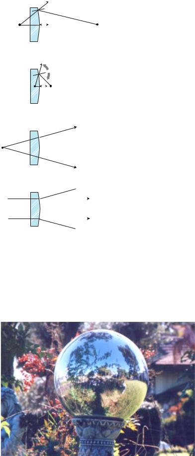
(a) |
Example: An anti-shoplifting mirror |
||||||||
Question: Convenience stores often install an out-bending |
|||||||||
I |
|
|
O |
mirror so that the clerk has a view of the whole store and can |
|||||
|
|
|
catch shoplifters. Use a ray diagram to show that the image is |
||||||
|
|
||||||||
|
|
|
|
|
|
||||
|
|
|
|
|
|
reduced, bringing more into the clerk’s field of view. If the focal |
|||
|
|
|
|
|
|
length of the mirror is 3.0 m, and the mirror is 7.0 m from the |
|||
|
|
|
|
|
|
farthest wall, how deep is the image of the store? (Note that in |
|||
|
|
|
|
|
|
the other method of handling the signs, the focal length would |
|||
(b) |
have been given as –3.0 m.) |
||||||||
Solution: As shown in ray diagram (a), di is less than do. The |
|||||||||
|
|
|
O |
||||||
I |
|
magnification, M = di/do, will be less than one, i.e. the image is |
|||||||
|
|
||||||||
|
|||||||||
|
|
|
|
|
|
actually reduced rather than magnified. |
|||
|
|
|
|
|
|
We now apply the method outlined above for determining the |
|||
|
|
|
|
|
|
plus and minus signs. Step 1: The object is the point on the |
|||
|
|
|
|
|
|
opposite wall. As an experiment, (b), we try making the object |
|||
|
|
|
|
|
|
closer — much much closer, so that even if our drawing isn’t |
|||
(c) |
|
|
|
|
|
perfectly accurate we’ll still get the right result for the change in |
|||
|
|
|
|
|
the image’s location. (I did these drawings using illustration |
||||
|
|
|
|
|
|
||||
I |
software, but if you were doing them by hand, you’d also want to |
||||||||
make much larger ones for greater accuracy.) The two angles at |
|||||||||
|
|
|
|
|
|
||||
|
|
|
|
|
|
||||
|
|
|
|
|
|
the mirror fan out from the normal. Increasing θo has clearly |
|||
|
|
|
|
|
|
made θi larger as well. (All four angles got bigger.) There must be |
|||
|
|
|
|
|
|
a cancellation of the effects of changing the two terms on the |
|||
(d) |
right in the same way, and the only way to get such a cancella- |
||||||||
tion is if the two terms in the angle equation have opposite signs: |
|||||||||
|
|
|
|
|
|
||||
|
|
|
|
|
|
θf |
= + θi |
– θo |
|
|
|
|
|
|
|
or |
|
|
|
|
|
|
|
|
|
θf |
= – θi |
+ θo . |
|
|
|
|
|
|
|
||||
Step 2: Now which is the positive term and which is negative? Figure (c) shows a perfectly reasonable ray diagram of an image formed of an object at infinity, the moon, for example. We have θo=0, since there is no angle between the rays arriving at the mirror from the object. Figure (d) shows an attempt to make an image at infinity. To get an image at infinity, we would have had to start with a converging set of rays, which is not physically possible, since diffuse reflection creates diverging rays. If θo can be zero, then the sign of the θi term must be positive.
An outbending mirror in the shape of a sphere. The image is reduced (minified), and is also distorted because the mirror’s curve is not shallow.
40 |
Chapter 3 Images by Reflection, Part II |