

B.Crowell - Optics, Vol
.5.pdfd
1
2
3


 w
w
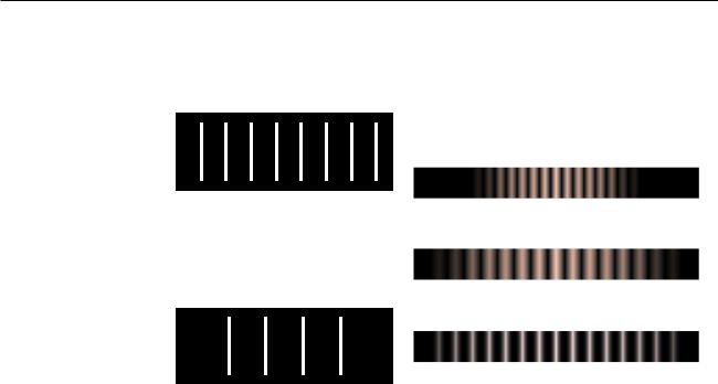
1.A diffraction pattern formed by a real double slit. The width of each slit is not negligible compared to the wavelength of the light. This is a real photo.
2.This idealized pattern is not likely to occur in real life. To get it, you would need each slit to be narrow compared to the wavelength of the light, but that’s not usually possible. This is not a real photo.
3.A real photo of a single-slit diffraction pattern caused by a slit whose width is the same as the widths of the slits used to make the top pattern.
(Photos by the author.)
Double-slit diffraction is easier to understand conceptually than singleslit diffraction, but if you do a double-slit diffraction experiment, in real life, you are likely to encounter a complicated pattern like pattern 1 in the figure above, rather than the simpler one, 2, you were expecting. This is because the slits are not narrower than the wavelength of the light being used. We really have two different distances in our pair of slits: d, the distance between the slits, and w, the width of each slit. Remember that smaller distances on the object the light diffracts around correspond to larger features of the diffraction pattern. The pattern 1 thus has two spacings in it: a short spacing corresponding to the large distance d, and a long spacing that relates to the small dimension w.
71
5.8ò* The Principle of Least Time
A B
(a) Light could take many different paths from A to B.
12.28
11.93
11.61
11.31
11.04
10.80
10.59
10.41
10.26
10.15
10.07
10.02
10.00
10.02
10.07
10.15
10.26
10.41
10.59
10.80
11.04
11.31
11.61
11.93
12.28
(b) The distance traveled along the 25 possible paths ranges from 10.00 wavelengths to 12.28.
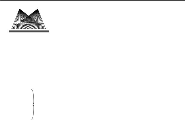
In sections 1.5 and 4.4, we saw how in the ray model of light, both refraction and reflection can be described in an elegant and beautiful way by a single principle, the principle of least time. We can now justify the principle of least time based on the wave model of light. Consider an example involving reflection, (a). Starting at point A, Huygens’ principle for waves tells us that we can think of the wave as spreading out in all directions. Suppose we imagine all the possible ways that a ray could travel from A to B. We show this by drawing 25 possible paths, of which the central one is the shortest. Since the principle of least time connects the wave model to the ray model, we should expect to get the most accurate results when the wavelength is much shorter than the distances involved — for the sake of this numerical example, let’s say that a wavelength is 1/10 of the shortest reflected path from A to B. The table, (b), shows the distances traveled by the 25 rays.
Note how similar are the distances traveled by the group of 7 rays, indicated with a bracket, that come closest to obeying the principle of least time. If we think of each one as a wave, then all 7 are again nearly in phase at point B. However, the rays that are farther from satisfying the principle of least time show more rapidly changing distances; on reuniting at point B, their phases are a random jumble, and they will very nearly cancel each other out. Thus, almost none of the wave energy delivered to point B goes by these longer paths. Physically we find, for instance, that a wave pulse emitted at A is observed at B after a time interval corresponding very nearly to the shortest possible path, and the pulse is not very “smeared out” when it gets there. The shorter the wavelength compared to the dimensions of the figure, the more accurate these approximate statements become.
Instead of drawing a finite number of rays, such 25, what happens if we think of the angle, θ, of emission of the ray as a continuously varying variable? Minimizing the distance L requires
dL = 0 . dθ
Because L is changing slowly in the vicinity of the angle that satisfies the principle of least time, all the rays that come out close to this angle have very nearly the same L, and remain very nearly in phase when they reach B. This is the basic reason why the discrete table, (b), turned out to have a group of rays that all traveleed nearly the same distance.
As discussed in section 1.5, the principle of least time is really a principle of least or greatest time. This makes perfect sense, since dL/dθ=0 can in general describe either a minimum or a maximum
The principle of least time is very general. It does not apply just to refraction and reflection — it can even be used to prove that light rays travel in a straight line through empty space, without taking detours! This general approach to wave motion was used by Richard Feynman, one of the pioneers who in the 1950’s reconciled quantum mechanics with relativity (book 6). A very readable explanation is given in a book Feynman wrote for laypeople, QED: The Strange Theory of Light and Matter.
72 |
Chapter 5 Wave Optics |

Summary
Selected Vocabulary |
|
diffraction ......................... |
the behavior of a wave when it encounters an obstacle or a nonuniformity |
|
in its medium; in general, diffraction causes a wave to bend around |
|
obstacles and make patterns of strong and weak waves radiating out |
|
beyond the obstacle. |
coherent ............................ |
a light wave whose parts are all in phase with each other |
Terminology Used in Other Books |
|
wavelets ............................. |
the ripples in Huygens’ principle |
Summary |
|
Wave optics is a more general theory of light than ray optics. When light interacts with material objects that are much larger then one wavelength of the light, the ray model of light is approximately correct, but in other cases the wave model is required.
Huygens’ principle states that, given a wavefront at one moment in time, the future behavior of the wave can be found by breaking the wavefront up into a large number of small, side-by-side wave peaks, each of which then creates a pattern of circular or spherical ripples. As these sets of ripples add together, the wave evolves and moves through space. Since Huygens’ principle is a purely geometrical construction, diffraction effects obey a simple scaling rule: the behavior is unchanged if the wavelength and the dimensions of the diffracting objects are both scaled up or down by the same factor. If we wish to predict the angles at which various features of the diffraction pattern radiate out, scaling requires that these angles depend only on the unitless ratio λ/d, where d is the size of some feature of the diffracting object.
Double-slit diffraction is easily analyzed using Huygens’ principle if the slits are narrower than one wavelength. We need only construct two sets of ripples, one spreading out from each slit. The angles of the maxima (brightest points in the bright fringes) and minima (darkest points in the dark fringes) are given by the equation
λ |
= |
sin θ |
, |
|
d |
m |
|||
|
|
where d is the center-to-center spacing of the slits, and m is an integer at a maximum or an integer plus 1/2 at a minimum.
If some feature of a diffracting object is repeated, the diffraction fringes remain in the same places, but become narrower with each repetition. By repeating a double-slit pattern hundreds or thousands of times, we obtain a diffraction grating.
A single slit can produce diffraction fringes if it is larger than one wavelength. Many practical instances of diffraction can be interpreted as single-slit diffraction, e.g. diffraction in telescopes. The main thing to realize about single-slit diffraction is that it exhibits the same kind of relationship between λ, d, and angles of fringes as in any other type of diffraction.
Summary 73
Homework Problems
1. Why would blue or violet light be the best for microscopy?
2. Match gratings A-C with the diffraction patterns 1-3 that they produce. Explain.
A |
1 |
|
B |
|
2 |
|
|
|
|
|
|
3
C
3 . The beam of a laser passes through a diffraction grating, fans out, and illuminates a wall that is perpendicular to the original beam, lying at a distance of 2.0 m from the grating. The beam is produced by a heliumneon laser, and has a wavelength of 694.3 nm. The grating has 2000 lines per centimeter. (a) What is the distance on the wall between the central maximum and the maxima immediately to its right and left? (b) How much does your answer change when you use the approximation
sin q » q ?
4. When white light passes through a diffraction grating, what is the smallest value of m for which the visible spectrum of order m overlaps the next one, of order m+1? (The visible spectrum runs from about 400 nm to about 700 nm.)
S |
A solution is given in the back of the book. |
↔ A difficult problem. |
|
A computerized answer check is available. |
ò A problem that requires calculus. |
74 |
Chapter 5 Wave Optics |

5. Ultrasound, i.e. sound waves with frequencies too high to be audible, can be used for imaging fetuses in the womb or for breaking up kidney stones so that they can be eliminated by the body. Consider the latter application. Lenses can be built to focus sound waves, but because the wavelength of the sound is not all that small compared to the diameter of the lens, the sound will not be concentrated exactly at the geometrical focal point. Instead, a diffraction pattern will be created with an intense central spot surrounded by fainter rings. About 85% of the power is concentrated within the central spot. The angle of the first minimum (surrounding the central spot) is given by sin θ = 1.22 λ/b, where b is the diameter of the lens. This is similar to the corresponding equation for a single slit, but with a factor of 1.22 in front which arises from the circular shape of the aperture. Let the distance from the lens to the patient's kidney stone be L=20 cm. You will want f>20 kHz, so that the sound is inaudible. Find values of b and f that would result in a usable design, where the central spot is small enough to lie within a kidney stone 1 cm in diameter.
6. For star images such as the ones in the photo in section 5.6, estimate the angular width of the diffraction spot due to diffraction at the mouth of the telescope. Assume a telescope with a diameter of 10 meters (the largest currently in existence), and light with a wavelength in the middle of the visible range. Compare with the actual angular size of a star of diameter 109 m seen from a distance of 1017 m. What does this tell you?
7. Under what circumstances could one get a mathematically undefined result by solving the double-slit diffraction equation for θ? Give a physical interpretation of what would actually be observed.
8. When ultrasound is used for medical imaging, the frequency may be as high as 5-20 MHz. Another medical application of ultrasound is for therapeutic heating of tissues inside the body; here, the frequency is typically 1-3 MHz. What fundamental physical reasons could you suggest for the use of higher frequencies for imaging?
9. The figure below shows two diffraction patterns, both made with the same wavelength of red light. (a) What type of slits made the patterns? Is it a single slit, double slits, or something else? Explain. (b) Compare the dimensions of the slits used to make the top and bottom pattern. Give a numerical ratio, and state which way the ratio is, i.e., which slit pattern was the larger one. Explain.
Homework Problems |
75 |
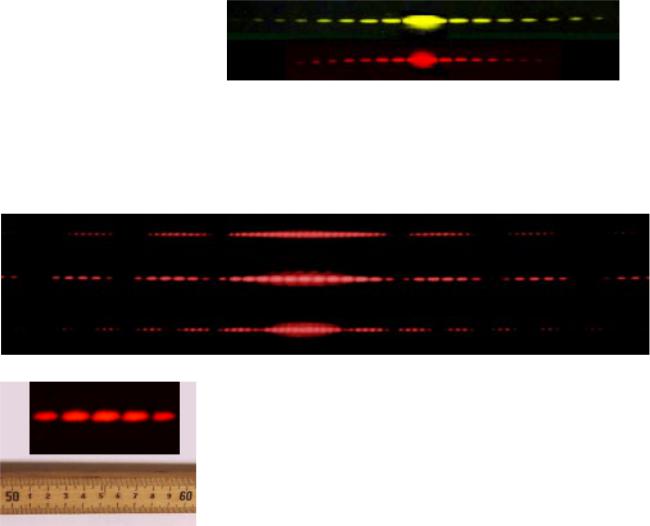
10. The figure below shows two diffraction patterns. The top one was made with yellow light, and the bottom one with red. Could the slits used to make the two patterns have been the same?
11. The figure below shows three diffraction patterns. All were made under identical conditions, except that a different set of double slits was used for each one. The slits used to make the top pattern had a center-to- center separation d=0.50 mm, and each slit was w=0.04 mm wide.
(a) Determine d and w for the slits used to make the pattern in the middle. (b) Do the same for the slits used to make the bottom pattern.
12. The figure shows a diffraction pattern made by a double slit, along with an image of a meter stick to show the scale. The slits were 146 cm away from the screen on which the diffraction pattern was projected. The spacing of the slits was 0.050 mm. What was the wavelength of the light?
13. Sketch the diffraction pattern from the figure on your paper. Now consider the four variables in the equation λ/d=sin θ/m. Which of these are the same for all five fringes, and which are different for each fringe? Which variable would you naturally use in order to label which fringe was which? Label the fringes on your sketch using the values of that variable.
Problems 12 and 13.
76
Exercises
Exercise 2A: Exploring Images With a Curved Mirror
Equipment:
curved mirrors like the ones described in this chapter curved mirrors that bulge outward (for part 6 only)
1. Obtain a curved mirror from your instructor. If it is silvered on both sides, make sure you’re working with the hollowed-out side, which bends light rays inward. Look at your own face in the mirror. Now change the distance between your face and the mirror, and see what happens. How do you explain your observations?
2. With the mirror held far away from you, observe the image of something behind you, over your shoulder. Now bring your eye closer and closer to the mirror. Can you see the image with your eye very close to the mirror? Explain what’s happening.
3. Now imagine the following new situation, but don’t actually do it yet. Suppose you lay the mirror face-up on a piece of tissue paper, put your finger 5 or 10 cm or so above the mirror, and look at the image of your finger. As in part 2, you can bring your eye closer and closer to the mirror.
Write down a prediction of what will happen. Will you be able to see the image with your eye very close to the mirror?
Prediction:_______________________________________________________
Now test your prediction. If your prediction was incorrect, can you explain your results?
4. Lay the mirror on the tissue paper, and use it to create an image of the overhead lights on a piece of paper above it and a little off to the side. What do you have to do in order to make the image clear? Can you explain this observation?
5. Now imagine the following experiment, but don’t do it yet. What will happen to the image on the paper if you cover half of the mirror with your hand?
Prediction:_______________________________________________________
Test your prediction. If your prediction was incorrect, can you explain what happened?
6. Now imagine forming an image with a curved mirror that bulges outward, and that therefore bends light rays away from the central axis. Draw a typical ray diagram. Is the image real or virtual? Will there be more than one type of image?
Prediction:_______________________________________________________
Test your prediction with the new type of mirror.
77
Exercise 3A: Object and Image Distances
Equipment:
optical benches inbending mirrors illuminated objects
1. Set up the optical bench with the mirror at zero on the centimeter scale. Set up the illuminated object on the bench as well.
2. Each group will locate the image for their own value of the object distance, by finding where a piece of paper has to be placed in order to see the image on it. (The instructor will do one point as well.) Note that you will have to tilt the mirror a little so that the paper on which you project the image doesn’t block the light from the illuminated object.
Is the image real or virtual? How do you know? Is it inverted or uninverted?
Draw a ray diagram.
3. Measure the image distance and write your result in the table on the board. Do the same for the magnification.
4. What do you notice about the trend of the data on the board? Draw a second ray diagram with a different object distance, and show why this makes sense. Some tips for doing this correctly: (1) For simplicity, use the point on the object that is on the mirror’s axis. (2) You need to trace two rays to locate the image. To save work, don’t just do two rays at random angles. You can either use the on-axis ray as one ray, or do two rays that come off at the same angle, one above and one below the axis. (3) Where each ray hits the mirror, draw the normal line, and make sure the ray is at equal angles on both sides of the normal.
5. We will find the mirror’s focal length from the instructor’s data-point. Then, using this focal length, calculate a theoretical prediction of the image distance, and write it on the board next to the experimentally determined image distance.
78
Exercise 4A: How strong are your glasses?
This exercise was created by Dan MacIsaac.
Equipment: eyeglasses
outbending lenses for students who don’t wear glasses, or who use inbending glasses rulers and metersticks
scratch paper marking pens
Most people who wear glasses have glasses whose lenses are outbending, which allows them to focus on objects far away. Such a lens cannot form a real image, so its focal length cannot be measured as easily as that of an inbending lens. In this exercise you will determine the focal length of your own glasses by taking them off, holding them at a distance from your face, and looking through them at a set of parallel lines on a piece of paper. The lines will be reduced (the lens’s magnification is less than one), and by adjusting the distance between the lens and the paper, you can make the magnification equal 1/2 exactly, so that two spaces between lines as seen through the lens fit into one space as seen simultaneously to the side of the lens. This object distance can be used in order to find the focal length of the lens.
1. Use a marker to draw three evenly spaced parallel lines on the paper. (A spacing of a few cm works well.)
2. Does this technique really measure magnification or does it measure angular magnification? What can you do in your experiment in order to make these two quantities nearly the same, so the math is simpler?
3. Before taking any numerical data, use algebra to find the focal length of the lens in terms of do, the object distance that results in a magnification of 1/2.
4. Measure the object distance that results in a magnification of 1/2, and determine the focal length of your lens.
79
Exercise 5A: Double-Source Interference
Equipment: ripple tank
ruler, protractor, and compass
1. Observe the wave pattern formed by a single source. Try adjusting the frequency at which the motor runs. What do you have to do to the frequency in order to increase the wavelength, and what do you have to do to decrease it?
2. Observe the interference pattern formed by two sources. For convenience, try to get your wavelength as close as possible to 1 cm. We’ll call this setup, with λ= 1 cm and d=2.5 cm, the default setup.
3. Imagine that you were to double the wavelength and double the distance between the sources. How would a snapshot of this wave pattern compare with a snapshot of the pattern made by the default setup? Based on this, how do you predict the angles of the maxima and minima will compare?
_______________
Test your predictions.
4. On a piece of paper, make a life-size drawing of the two sources in the default setup, and locate the following points:
A.The point that is 10 wavelengths from source #1 and 10 wavelengths from source #2.
B.The point that is 11 wavelengths from #1 and 11 from #2.
C.The point that is 10 wavelengths from #1 and 10.5 from #2.
D.The point that is 11 wavelengths from #1 and 11.5 from #2.
E.The point that is 10 wavelengths from #1 and 11 from #2.
F.The point that is 11 wavelengths from #1 and 12 from #2.
What do these points correspond to in the real wave pattern?
5. Make a fresh copy of your drawing, showing only point E and the two sources, which form a long, skinny triangle. Now suppose you were to change the default setup by doubling d, while leaving λ the same. Realistically this involves moving one peg over one hole, while leaving the other peg in the same place, but it’s easier to understand what’s happening on the drawing if you move both sources outward, keeping the center fixed. Based on your drawing, what will happen to the position of point E when you double d? How has the angle of point E changed?___________________
Test your prediction.
6. In the previous part of the exercise, you saw the effect of doubling d while leaving λ the same. Now what do you think would happen to your angles if, starting from the standard setup, you doubled λ while leaving d the same?_________________
Try it.
7. Suppose λ was a millionth of a centimeter, while d was still as in the standard setup. What would happen to the angles? What does this tell you about observing diffraction of light?
______________
80