

B.Crowell - Optics, Vol
.5.pdfWe have now determined that the form of the angle equation
must be
θf = θi – θo ,
and the signs of the distance equation must behave the same way:
1 |
= |
|
1 |
– |
1 |
. |
|||
|
|
|
|
||||||
f |
|
|
|
di |
do |
||||
Solving for di, we find |
|
|
|
|
|
|
|
||
d |
|
= |
1 + |
|
1 |
– 1 |
|||
|
|
|
|||||||
|
i |
|
|
f |
|
do |
|||
|
|
|
|
|
|
|
|
|
|
|
|
= |
2.1 m . |
||||||
The image of the store is reduced by a factor of 2.1/7.0=0.3, i.e. it is smaller by 70%.
Example: A shortcut for real images
In the case of a real image, there is a shortcut for step 1, the determination of the signs. In a real image, the rays cross at both the object and the image. We can therefore time-reverse the ray diagram, so that all the rays are coming from the image and reconverging at the object. Object and image swap roles. Due to this time-reversal symmetry, the object and image cannot be treated differently in any of the equations, and they must therefore have the same signs. They are both positive, since they must add up to a positive result.
3.3* Aberrations
spherical
parabolic
Spherical mirrors are the cheapest to make, but parabolic mirrors are better for making images of objects at infinity. A sphere has equal curvature everywhere, but a parabola has tighter curvature at its center and gentler curvature at the sides.
An imperfection or distortion in an image is called an aberration. An aberration can be produced by a flaw in a lens or mirror, but even with a perfect optical surface some degree of aberration is unavoidable. To see why, consider the mathematical approximation we’ve been making, which is that the depth of the mirror’s curve is small compared to do and di. Since only a flat mirror can satisfy this shallow-mirror condition perfectly, any curved mirror will deviate somewhat from the mathematical behavior we derived by assuming that condition. There are two main types of aberration in curved mirrors, and these also occur with lenses.
(1)The image may be sharp when the object is at certain distances and blurry when it is at other distances. The blurriness occurs because the rays do not all cross at exactly the same point. If we know in advance the distance of the objects with which the mirror or lens will be used, then we can optimize the shape of the optical surface to make in-focus images in that situation. For instance, a spherical mirror will produce a perfect image of an object that is at the center of the sphere, because each ray is reflected directly onto the radius along which it was emitted. For objects at greater distances, however, the focus will be somewhat blurry. In astronomy the objects being used are always at infinity, so a spherical mirror is a poor choice for a telescope. A different shape (a parabola) is better specialized for astronomy.
(2)An object on the axis of the lens or mirror may be imaged correctly, but off-axis objects may be out of focus. In a camera, this type of aberration would show up as a fuzziness near the sides of the picture when the center was perfectly focused.
Section 3.3* Aberrations |
41 |
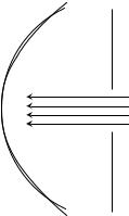
Even though the spherical mirror (solid line) is not well adapted for viewing an object at infinity, we can improve its performance greatly by stopping it down. Now the only part of the mirror being used is the central portion, where its shape is virtually indistinguishable from a parabola (dashed line).
One way of decreasing aberration is to use a small-diameter mirror or lens, or block most of the light with an opaque screen with a hole in it, so that only light that comes in close to the axis can get through. Either way, we are using a smaller portion of the lens or mirror whose curvature will be more shallow, thereby making the shallow-mirror (or thin-lens) approximation more accurate. Your eye does this by narrowing down the pupil to a smaller hole. In a camera, there is either an automatic or manual adjustment, and narrowing the opening is called “stopping down.” The disadvantage of stopping down is that light is wasted, so the image will be dimmer or a longer exposure must be used.
What I would suggest you take away from this discussion for the sake of your general scientific education is simply an understanding of what an aberration is, why it occurs, and how it can be reduced, not detailed facts about specific types of aberrations.
42 |
Chapter 3 Images by Reflection, Part II |

Summary
Selected Vocabulary |
|
focal length........................ |
a property of a lens or mirror, equal to the distance from the lens or mirror |
|
to the image it forms of an object that is infinitely far away |
Notation |
|
f ......................................... |
the focal length |
do ....................................... |
the distance of the object from the mirror (technically from the plane |
|
tangent to the center of the mirror, although this seldom matters much for |
|
a mirror whose curve is shallow) |
di ....................................... |
the distance of the image from the mirror |
θf ....................................... |
the focal angle, defined as 1/f |
θo ...................................... |
the object angle, defined as 1/do |
θi ....................................... |
the image angle, defined as 1/di |
Notation Used in Other Books |
|
f>0..................................... |
describes an inbending lens or mirror; in this book, all focal lengths are |
|
positive, so there is no such implication |
f<0..................................... |
describes an out-bending lens or mirror; in this book, all focal lengths are |
|
positive |
M<0 .................................. |
indicates an inverted image |
Summary |
|
Every lens or mirror has a property called the focal length, which is defined as the distance from the lens or mirror to the image it forms of an object that is infinitely far away. A stronger lens or mirror has a shorter focal length.
The relationship between the locations of an object and its image formed by a lens or mirror can always be expressed by equations of the form
θf |
= ± θi ± θo |
|
||||
1 |
= |
± |
1 |
± |
1 |
, |
|
d o |
|||||
f |
|
|
d i |
|
||
The choice of plus and minus signs depends on whether we are dealing with a lens or a mirror, whether the lens or mirror is inbending or outbending, and whether the image is real or virtual. A method for determining the plus and minus signs is as follows:
1.Use ray diagrams to decide whether θi and θo vary in the same way or in opposite ways. Based on this, decide whether the two signs in the equation are the same or opposite. If the signs are opposite, go on to step 2 to determine which is positive and which is negative.
2.It is normally only physically possible for either θi or θo to be zero, not both. Imagine the case where that variable is zero. Since the left-hand side of the equation is positive by definition, the term on the right that we didn’t eliminate must be the one that has a plus sign.
Once the correct form of the equation has been determined, the magnification can be found via the equation
M = |
di |
. |
|
do |
|||
|
|
Summary 43
Homework Problems
1. Apply the equation M=di/do to the case of a flat mirror.
2 S. Use the method described in the text to derive the equation relating object distance to image distance for the case of a virtual image produced by an inbending mirror.
3. (a) Make up a numerical example of a virtual image formed by an inbending mirror with a certain focal length, and determine the magnification. (You will need the result of the previous problem.) Now change the location of the object a little bit and redetermine the magnification, showing that it changes. At my local department store, the cosmetics department sells mirrors advertised as giving a magnification of 5 times. How would you interpret this?
(b↔) Suppose a Newtonian telescope is being used for astronomical observing. Assume for simplicity that no eyepiece is used, and assume a value for the focal length of the mirror that would be reasonable for an amateur instrument that is to fit in a closet. Is the angular magnification different for the moon than for a distant galaxy?
4. (a) Find a case where the magnification of a curved mirror is infinite. Is the angular magnification infinite from any realistic viewing position? (b) Explain why an arbitrarily large magnification can’t be achieved by having a sufficiently small value of do.
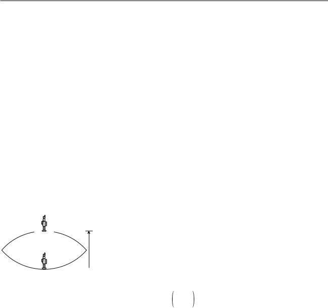
5↔. The figure shows a device for constructing a realistic optical illusion. Two mirrors of equal focal length are put against each other with their silvered surfaces facing inward. A small object placed in the bottom of the
cavity will have its image projected in the air above. The way it works is that the top mirror produces a virtual image, and the bottom mirror then
h creates a real image of the virtual image. (a) Show that if the image is to be positioned as shown, at the mouth of the cavity, then the focal length of  the mirrors is related to the dimension h via the equation
Problem 5. |
1 |
= |
1 |
+ |
|
|
1 |
|
|
. |
|
|
|
|
|
||||||
|
h |
|
|
|
|
– 1 |
||||
|
f |
|
|
h + |
1 |
– |
1 |
|
||
|
|
|
|
|
h |
|
|
|||
|
|
|
|
|
|
|
f |
|
|
(b) Restate the equation in terms of a single variable x=h/f, and show that there are two solutions for x. Which solution is physically consistent with the assumptions of the calculation?
6. A hollowed-out surface that reflects sound waves can act just like an inbending mirror. Suppose that, standing near such a surface, you are able to find point where you can place your head so that your own whispers are focused back on your head, so that they sound loud to you. Given your distance to the surface, what is the surface’s focal length?
S |
A solution is given in the back of the book. |
↔ A difficult problem. |
|
A computerized answer check is available. |
ò A problem that requires calculus. |
44 |
Chapter 3 Images by Reflection, Part II |
4 Refraction and Images
Economists normally consider free markets to be the natural way of judging the monetary value of something, but social scientists also use questionnaires to gauge the relative value of privileges, disadvantages, or possessions that cannot be bought or sold. They ask people to imagine that they could trade one thing for another and ask which they would choose. One interesting result is that the average light-skinned person in the U.S. would rather lose an arm than suffer the racist treatment routinely endured by African-Americans. Even more impressive is the value of sight. Many prospective parents can imagine without too much fear having a deaf child, but would have a far more difficult time coping with raising a blind one.
So great is the value attached to sight that some have imbued it with mystical aspects. Moses “had vision,” George Bush did not. Christian fundamentalists who perceive a conflict between evolution and their religion have claimed that the eye is such a perfect device that it could never have arisen through a process as helter-skelter as evolution, or that it could not have evolved because half of an eye would be useless. In fact, the structure of an eye is fundamentally dictated by physics, and it has arisen separately by evolution somewhere between eight and 40 times, depending
45
on which biologist you ask. We humans have a version of the eye that can be traced back to the evolution of a light-sensitive “eye spot” on the head of an ancient invertebrate. A sunken pit then developed so that the eye would only receive light from one direction, allowing the organism to tell where the light was coming from. (Modern flatworms have this type of eye.) The top of the pit then became partially covered, leaving a hole, for even greater directionality (as in the nautilus). At some point the cavity became filled with jelly, and this jelly finally became a lens, resulting in the general type of eye that we share with the bony fishes and other vertebrates. Far from being a perfect device, the vertebrate eye is marred by a serious design flaw due to the lack of planning or intelligent design in evolution: the nerve cells of the retina and the blood vessels that serve them are all in front of the lightsensitive cells, blocking part of the light. Squids and other molluscs, whose eyes evolved on a separate branch of the evolutionary tree, have a more sensible arrangement, with the light-sensitive cells out in front.
4.1Refraction
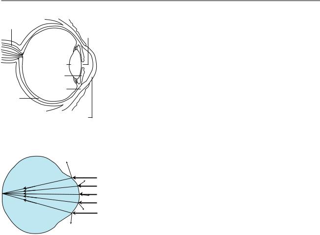
optic nerve
pupil
lens
iris
sclera
retina
cornea
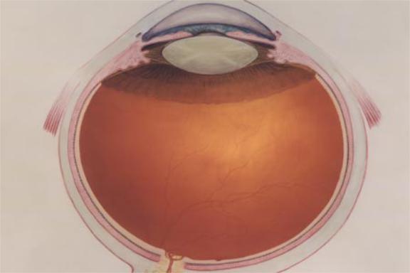
(a) The anatomy of the human eye.
(After an uncopyrighted diagram by the National Eye Institute, NIH.)
(b) A simplified optical diagram of the eye. Light rays are bent when they cross from the air into the eye.
Refraction
The fundamental physical phenomenon at work in the eye is that when light crosses a boundary between two media (such as air and the eye’s jelly), part of its energy is reflected, but part passes into the new medium. In the ray model of light, we describe the original ray as splitting into a reflected ray and a transmitted one (the one that gets through the boundary). Of course the reflected ray goes in a direction that is different from that of the original one, according to the rules of reflection we have already studied. More surprisingly — and this is the crucial point for making your eye focus light — the transmitted ray is bent somewhat as well. This bending phenomenon is called refraction. The origin of the word is the same as that of the word “fracture,” i.e. the ray is bent or “broken.” (Keep in mind, however, that light rays are not physical objects that can really be “broken.”) Refraction occurs with all waves, not just light waves.
The actual anatomy of the eye, (a), is quite complex, but in essence it is very much like every other optical device based on refraction. The rays are bent when they pass through the front surface of the eye. Rays that enter farther from the central axis are bent more, with the result that an image is formed on the retina. There is only one slightly novel aspect of the situation. In most human-built optical devices, such as a movie projector, the light is bent as it passes into a lens, bent again as it reemerges, and then reaches a focus beyond the lens. In the eye, however, the “screen” is inside the eye, so the rays are only refracted once, on entering the jelly, and never emerge again.
A common misconception is that the “lens” of the eye is what does the focusing. All the transparent parts of the eye are made of fairly similar stuff, so the dramatic change in medium is when a ray crosses from the air into the eye (at the outside surface of the cornea). This is where nearly all the refraction takes place. The lens medium differs only slightly in its optical properties from the rest of the eye, so very little refraction occurs as light enters and exits the lens. The lens, whose shape is adjusted by muscles attached to it, is only meant for fine-tuning the focus to form images of near or far objects.
46 |
Chapter 4 Refraction and Images |
incident ray |
reflected ray |
medium 1
medium 2
transmitted ray
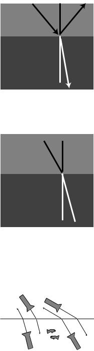
(c) The incident, reflected, and refracted rays all lie in a plane that includes the normal (dashed line).
θ1
medium 1 medium 2
θ2
(d) The angles θ1 and θ2 are related to each other, and also depend on the properties of the two media. Because refraction is time-reversal symmetric, there is no need to label the rays with arrowheads.
air
water
(e) Refraction has time-reversal symmetry. Regardless of whether the light is going in or out of the water, the relationship between the two angles is the same, and the ray is closer to the normal while in the water.
Refractive properties of media
What are the rules governing refraction? The first thing to observe is that just as with reflection, the new, bent part of the ray lies in the same plane as the normal (perpendicular) and the incident ray, (c).
If you try shooting a beam of light at the boundary between two substances, say water and air, you’ll find that regardless of the angle at which you send in the beam, the part of the beam in the water is always closer to the normal line, (d). It doesn’t matter if the ray is entering the water or leaving, so refraction is symmetric with respect to time-reversal, (e).
If, instead of water and air, you try another combination of substances, say plastic and gasoline, again you’ll find that the ray’s angle with respect to the normal is consistently smaller in one and larger in the other. Also, we find that if substance A has rays closer to normal than in B, and B has rays closer to normal than in C, then A has rays closer to normal than C. This means that we can rank-order all materials according to their refractive properties. Isaac Newton did so, including in his list many amusing substances, such as “Danzig vitriol” and “a pseudo-topazius, being a natural, pellucid, brittle, hairy stone, of a yellow color.” Several general rules can be inferred from such a list:
•Vacuum lies at one end of the list. In refraction across the interface between vacuum and any other medium, the other medium has rays closer to the normal.
•Among gases, the ray gets closer to the normal if you increase the density of the gas by pressurizing it more.
•The refractive properties of liquid mixtures and solutions vary in a smooth and systematic manner as the proportions of the mixture are changed.
•Denser substances usually, but not always, have rays closer to the normal.
The second and third rules provide us with a method for measuring the density of an unknown sample of gas, or the concentration of a solution. The latter technique is very commonly used, and the CRC Handbook of Physics and Chemistry, for instance, contains extensive tables of the refractive properties of sugar solutions, cat urine, and so on.
Section 4.1 Refraction |
47 |
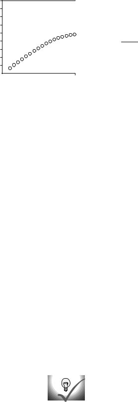
θwater (degrees)
90
80
70
60
50
40
30
20
10
0 


 0 10 20 30 40 50 60 70 80 90
θair (degrees)
Snell’s law
The numerical rule governing refraction was discovered by Snell, who must have collected experimental data something like what is shown on this graph and then attempted by trial and error to find the right equation. The equation he came up with was
sin θ1
sin θ2 = constant .
The value of the constant would depend on the combination of media used. For instance, any one of the data points in the graph would have sufficed to show that the constant was 1.3 for an air-water interface (taking air to be substance 1 and water to be substance 2).
Snell further found that if media A and B gave a constant KAB and media B and C gave a constant KBC, then refraction at an interface between A and C would be described by a constant equal to the product, KAC=KABKBC. This is exactly what one would expect if the constant depended on the ratio of some number characterizing one medium to the number characteristic of the second medium. This number is called the index of refraction of the medium, written as “n” in equations. Since measuring the angles would only allow him to determine the ratio of the indices of refraction of two media, Snell had to pick some medium and define it as having n=1. He chose to define vacuum as having n=1. (The index of refraction of air at normal atmospheric pressure is 1.0003, so for most purposes it is a good approximation to assume that air has n=1.) He also had to decide which way to define the ratio, and he chose to define it so that media with their rays closer to the normal would have larger indices of refraction. This had the advantage that denser media would typically have higher indices of refraction, and for this reason the index of refraction is also referred to as the optical density. Written in terms of indices of refraction, Snell’s equation becomes
sin θ1 |
= |
n 2 |
, |
sin θ2 |
n 1 |
but rewriting it in the form |
|
n1 sin θ1 = n2 sin θ2 |
[relationship between angles of rays at the |
|
interface between media with indices of |
|
refraction n1 and n2; angles are defined with |
|
respect to the normal] |
makes us less likely to get the 1’s and 2’s mixed up, so this the way most people remember Snell’s law. A few indices of refraction are given in the back of the book.
Self-Check
(1) What would the graph look like for two substances with the same index of refraction?
(2) Based on the graph, when does refraction at an air-water interface change the direction of a ray most strongly?
[Answers on next page.]
48 |
Chapter 4 Refraction and Images |
|
|
|
Example |
|
|
|
|
|
|
|
|
Question: A submarine shines its searchlight up toward the |
|||||
|
|
|||||||
|
|
|
surface of the water. What is the angle θ shown in the figure? |
|||||
|
α |
|
Solution: The tricky part is that Snell’s law refers to the angles |
|||||
|
|
with respect to the normal. Forgetting this is a very common |
||||||
|
60° |
|
mistake. The beam is at an angle of 30° with respect to the |
|||||
|
|
normal in the water. Let’s call the air medium 1 and the water |
||||||
|
|
|
||||||
|
|
|
medium 2. Solving Snell’s law for θ1, we find |
|||||
|
|
|
θ |
1 |
= |
sin– 1 |
n2 |
sin θ2 |
|
|
|
||||||
|
|
|
|
|||||
|
|
|
|
|
|
n1 |
||
θ2
medium 2 medium 1
 θ1
θ1
As mentioned above, air has an index of refraction very close to 1, and water’s is about 1.3, so we find θ1=40°. The angle α is therefore 50°.
The index of refraction is related to the speed of light
What neither Snell nor Newton knew was that there is a very simple interpretation of the index of refraction. This may come as a relief to the reader who is taken aback by the complex reasoning involving proportionalities that led to its definition. Later experiments showed that the index of refraction of a medium was inversely proportional to the speed of light in that medium. Since c is defined as the speed of light in vacuum, and n=1 is defined as the index of refraction of vacuum, we have
n = c/v . |
[n = medium’s index of refraction, v = speed of |
|
light in that medium, c=speed of light in a |
|
vacuum] |
Many textbooks start with this as the definition of the index of refraction, although that approach makes the quantity’s name somewhat of a mystery, and leaves students wondering why c/v was used rather than v/c. It should also be noted that measuring angles of refraction is a far more practical method for determining n than direct measurement of the speed of light in the substance of interest.
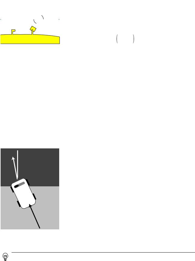
A mechanical model of Snell’s law
Why should refraction be related to the speed of light? The mechanical model shown in the figure may help to make this more plausible. Suppose medium 2 is thick, sticky mud, which slows down the car. The car’s right wheel hits the mud first, causing the right side of the car to slow down. This will cause the car to turn to the right until is moves far enough forward for the left wheel to cross into the mud. After that, the two sides of the car will once again be moving at the same speed, and the car will go straight.
Of course, light isn’t a car. Why should a beam of light have anything resembling a “left wheel” and “right wheel?” After all, the mechanical model would predict that a motorcycle would go straight, and a motorcycle seems like a better approximation to a ray of light than a car. The whole thing is just a model, not a description of physical reality.
(1)If n1 and n2 are equal, Snell’s law becomes sin θ1=sin θ2, which implies θ1=θ2. The graph would be a straight line along the diagonal of the graph.
(2)The graph is farthest from the diagonal when the angles are large, i.e. when the ray strikes the interface at an oblique or grazing angle.
Section 4.1 Refraction |
49 |
motion of wave 2
h λ1
λ2
 motion of wave 1
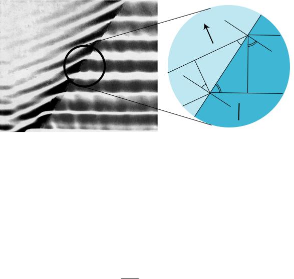
(a) Refraction of a water wave. The water in the upper left part of the tank is shallower, so the speed of the waves is slower there, and their wavelength is shorter. The reflected part of the wave is also very faintly visible.
Retouched from an uncopyrighted PSSC College Physics photograph.
(b) A close-up view of what happens at the interface between the deeper medium and the shallower medium. The dashed lines are normals to the interface. The two marked angles on
the right side are both equal to θ1, and the two on the left equal
θ2.
A derivation of Snell’s law
However intuitively appealing the mechanical model may be, light is a wave, and we should be using wave models to describe refraction. In fact Snell’s law can be derived quite simply from wave concepts. In figure (b), trigonometry gives
sin θ1 = λ1/h and sin θ2 = λ2/h .
Eliminating h by dividing the equations, we find
sin θ1 = λ1 sin θ2 λ2 .
The frequencies of the two waves must be equal or else they would get out of step, so by v=fλ we know that their wavelengths are proportional to their
velocities. Combining λv with v 1/n gives λ1/n , so we find
sin θ1 |
= |
n 2 |
, |
sin θ2 |
n 1 |
which is one form of Snell’s law.
Example: Ocean waves near and far from shore
Ocean waves are formed by winds, typically on the open sea, and the wavefronts are perpendicular to the direction of the wind that formed them. At the beach, however, you have undoubtedly observed that waves tend come in with their wavefronts very nearly (but not exactly) parallal to the shoreline. This is because the speed of water waves in shallow water depends on depth: the shallower the water, the slower the wave. Althoughthe change from the fast-wave region to the slow-wave region is gradual rather than abrupt, there is still refraction, and the wave motion is nearly perpendicular to the normal in the slow region.
50 |
Chapter 4 Refraction and Images |