

B.Crowell - Optics, Vol
.5.pdfTotal internal reflection in a fiber-optic cable.
Color and refraction
In general, the speed of light in a medium depends both on the medium and on the wavelength of the light. Another way of saying it is that a medium’s index of refraction varies with wavelength. This is why a prism can be used to split up a beam of white light into a rainbow. Each wavelength of light is refracted through a different angle.
How much light is reflected, and how much is transmitted?
In book 3 we developed an equation for the percentage of the wave energy that is transmitted and the percentage reflected at a boundary between media. This was only done in the case of waves in one dimension, however, and rather than discuss the full three dimensional generalization it will be more useful to go into some qualitative observations about what happens. First, reflection happens only at the interface between two media, and two media with the same index of refraction act as if they were a single medium. Thus, at the interface between media with the same index of refraction, there is no reflection, and the ray keeps going straight. Continuing this line of thought, it is not surprising that we observe very little reflection at an interface between media with similar indices of refraction.
The next thing to note is that it is possible to have situations where no possible angle for the refracted ray can satisfy Snell’s law. Solving Snell’s law for θ2, we find
θ2 |
= sin |
– 1 |
n 1 |
sin θ1 |
, |
|
n 2 |
||||||
|
|
|
|
|
and if n1 is greater than n2, then there will be large values of θ1 for which the quantity (n1/n2) sin θ is greater than one, meaning that your calculator will flash an error message at you when you try to take the inverse sine. What can happen physically in such a situation? The answer is that all the light is reflected, so there is no refracted ray. This phenomenon is known as total internal reflection, and is used in the fiber-optic cables that nowadays carry almost all long-distance telephone calls. The electrical signals from your phone travel to a switching center, where they are converted from electricity into light. From there, the light is sent across the country in a thin transparent fiber. The light is aimed straight into the end of the fiber, and as long as the fiber never goes through any turns that are too sharp, the light will always encounter the edge of the fiber at an angle sufficiently oblique to give total internal reflection. If the fiber-optic cable is thick enough, one can see an image at one end of whatever the other end is pointed at.
Alternatively, a bundle of cables can be used, since a single thick cable is too hard to bend. This technique for seeing around corners is useful for making surgery less traumatic. Instead of cutting a person wide open, a surgeon can make a small “keyhole” incision and insert a bundle of fiberoptic cable (known as an endoscope) into the body.
Since rays at sufficiently large angles with respect to the normal may be completely reflected, it is not surprising that the relative amount of reflection changes depending on the angle of incidence, and is greatest for large angles of incidence.
Section 4.1 Refraction |
51 |
Discussion questions
A. What index of refraction should a fish have in order to be invisible?
B. Does a surgeon using an endoscope need a source of light inside the body
cavity? If so, how could this be done without inserting a light bulb through the incision?
C. A denser sample of a gas has a higher index of refraction than a less dense sample (i.e. a sample under lower pressure), but why would it not make sense for the index of refraction of a gas to be proportional to density?
D. The earth’s atmosphere gets thinner and thinner as you go higher in altitude. If a ray of light comes from a star that is below the zenith, what will happen to it as it comes into the earth’s atmosphere?
E. Does total internal reflection occur when light in a denser medium encounters a less dense medium, or the other way around? Or can it occur in either case?
4.2 Lenses
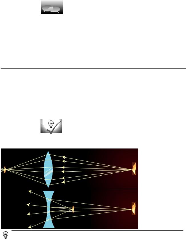
Figures (a) and (b) show examples of lenses forming images. There is essentially nothing for you to learn about imaging with lenses that is truly new. You already know how to construct and use ray diagrams, and you know about real and virtual images. The concept of the focal length of a lens is the same as for a curved mirror. The equations for locating images and determining magnifications are of the same form. It’s really just a question of flexing your mental muscles on a few examples. The following self-checks and discussion questions will get you started.
Self-Checks
(1) In figures (a) and (b), classify the images as real or virtual.
(2) Glass has an index of refraction that is greater than that of air. Consider the
topmost ray in figure (a). Explain why the ray makes a slight left turn upon entering the lens, and another left turn when it exits.
(3) If the flame in figure (b) was moved closer to the lens, what would happen to the location of the image?
(a) An inbending lens is making an image of a candle flame.
(b) Now an outbending lens is making an image of the flame.
(1) In (a), the rays cross at the image, so it is real. In (b), the rays only appear to have come from the image point, so the image is virtual.
(2)A ray is always closer to the normal in the medium with the higher index of refraction. The first left turn makes the ray closer to the normal, as it should be in glass. The second left turn makes the ray farther from the normal, which is how it should be in air.
(3)Take the topmost ray as an example. It will still take two right turns, but since it is entering the lens at a steeper angle, it will also leave at a steeper angle. Tracing backward to image, the steeper lines will meet closer to the lens.
52 |
Chapter 4 Refraction and Images |
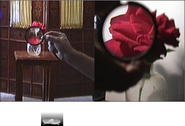
(c) Two images of a rose created by the same lens and recorded with the same camera.
Discussion Questions
A. In figures (a) and (b), the front and back surfaces are parallel to each other
at the center of the lens. What will happen to a ray that enters near the center,
but not necessarily along the axis of the lens?
B. Suppose you wanted to change the setup in figure (a) so that the location of the actual flame in the figure would instead be occupied by an image of a flame. Where would you have to move the candle to achieve this? What about in (b)?
C. There are three qualitatively different types of image formation that can occur with lenses, of which figures (a) and (b) exhaust only two. Figure out what the third possibility is. Which of the three possibilities can result in a magnification greater than one?
D. Classify the examples shown in figure (c) according to the types of images delineated in the previous discussion question.
E. In figures (a) and (b), the only rays drawn were those that happened to enter the lenses. Discuss this in relation to figure (c).
F. In the right-hand side of figure (c), the image viewed through the lens is in focus, but the side of the rose that sticks out from behind the lens is not. Why? G. In general, the index of refraction depends on the color of the light. What effect would this have on images formed by lenses?
Section 4.2 Lenses |
53 |
4.3* The Lensmaker’s Equation
The focal length of a spherical mirror is simply r/2, but we cannot expect the focal length of a lens to be given by pure geometry, since it also depends on the index of refraction of the lens. Suppose we have a lens whose front and back surfaces are both spherical. (This is no great loss of generality, since any surface with a sufficiently shallow curvature can be approximated with a sphere.) Then if the lens is immersed in a medium with an index of refraction of 1, its focal length is given approximately by
f = |
|
(n–1) |
|
1 |
± |
1 |
|
|
|
|
– 1 |
|
|
|
|
|
|
||||||||
|
|
|
||||||||||
|
|
|
|
|
|
. |
||||||
|
r 2 |
|||||||||||
|
|
|
|
r 1 |
|
|
|
|
|
|||
|
|
|
|
|
|
|
|
|
|
|
|
|
This is known as the lensmaker’s equation. In my opinion it is not particularly worthy of memorization. The positive sign is used when both surfaces are curved outward or both are curved inward; otherwise a negative sign applies. The proof of this equation is left as an exercise to those readers who are sufficiently brave and motivated.
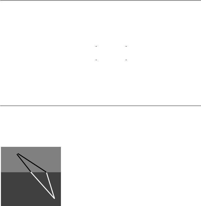
4.4* Refraction and the Principle of Least Time
A
faster slower
We seen previously how the rules governing straight-line motion of light and reflection of light can be derived from the principle of least time. What about refraction? In the figure, it is indeed plausible that the bending of the ray serves to minimize the time required to get from a point A to point B. If the ray followed the unbent path shown with a dashed line, it would have to travel a longer distance in the medium in which its speed is slower. By bending the correct amount, it can reduce the distance it has to cover in the slower medium without going too far out of its way. It is true that Snell’s law gives exactly the set of angles that minimizes the time required for light to get from one point to another. The proof of this fact is left as an exercise.
B
54 |
Chapter 4 Refraction and Images |

Summary
Selected Vocabulary |
|
refraction ........................... |
the change in direction that occurs when a wave encounters the interface |
|
between two media |
index of refraction ............. |
an optical property of matter; the speed of light in a vacuum divided by |
|
the speed of light in the substance in question |
Notation |
|
n ........................................ |
the index of refraction |
Summary |
|
Refraction is change in direction that occurs when a wave encounters the interface between two media. Together, refraction and reflection account for the basic principles behind nearly all optical devices.
Snell discovered the equation for refraction,
n1sin θ1 = n2sin θ2 |
[angles measured with respect to the normal] |
through experiments with light rays, long before light was proven to be a wave. Snell’s law can be proven based on the geometrical behavior of waves. Here n is the index of refraction. Snell invented this quantity to describe the refractive properties of various substances, but it was later found to be related to the speed of light in the substance,
n = c/v ,
where c is the speed of light in a vacuum. In general a material’s index of refraction is different for different wavelengths of light.
As discussed in the third book of this series, any wave is partially transmitted and partially reflected at the boundary between two media in which its speeds are different. It is not particularly important to know the equation that tells what fraction is transmitted (and thus refracted), but important technologies such as fiber optics are based on the fact that this fraction becomes zero for sufficiently oblique angles. This phenomenon is referred to as total internal reflection. It occurs when there is no angle that satisfies Snell’s law.
Summary 55

Homework Problems
1. Suppose an inbending lens is constructed of a type of plastic whose index of refraction is less than that of water. How will the lens’s behavior be different if it is placed underwater?
2. There are two main types of telescopes, refracting (using lenses) and reflecting (using mirrors). (Some telescopes use a mixture of the two types of elements: the light first encounters a large curved mirror, and then goes through an eyepiece that is a lens.) What implications would the colordependence of focal length have for the relative merits of the two types of telescopes? What would happen with white starlight, for example?
3. Based on Snell's law, explain why rays of light passing through the edges of an inbending lens are bent more than rays passing through parts closer to the center. It might seem like it should be the other way around, since the rays at the edge pass through less glass — shouldn't they be affected less?
4. By changing the separation distance between lens and film, a camera can focus on subjects at a variety of distances. Suppose the proper lensfilm separation for taking an in-focus picture of a distant object such as the moon is x. To take an in-focus picture of a nearby object, will the proper lens-film separation be greater than, equal to, or less than x? Explain using diagrams. [Based on a problem by Eugene Hecht.]
5 ↔. (a) Light is being reflected diffusely from an object 1.000 m under water. The light that comes up to the surface is refracted at the water-air interface. If the refracted rays all appear to come from the same point, then there will be a virtual image of the object in the water, above the object’s actual position, which will be visible to an observer above the water. Consider three rays, A, B and C, whose angles in the water with respect to the normal are qi=0.000°, 1.000° and 20.000° respectively. Find the depth of the point at which the refracted parts of A and B appear to have intersected, and do the same for A and C. Show that the intersections are at nearly the same depth, but not quite. [Check: The difference in depth should be about 4 cm.]
(b)Since all the refracted rays do not quite appear to have come from the same point, this is technically not a virtual image. In practical terms, what effect would this have on what you see?
(c)In the case where the angles are all small, use algebra and trig to show that the refracted rays do appear to come from the same point, and find an equation for the depth of the virtual image. Do not put in any numerical values for the angles or for the indices of refraction — just keep them as
symbols. You will need the approximation sin q » tan q » q , which is valid for small angles measured in radians.
S |
A solution is given in the back of the book. |
↔ A difficult problem. |
|
A computerized answer check is available. |
ò A problem that requires calculus. |
56 |
Chapter 4 Refraction and Images |
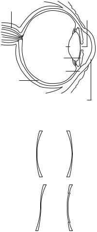
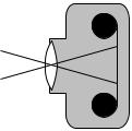
optic nerve
pupil
lens
iris
sclera
retina
cornea
Problem 6.
1 2
3 4
Problem 8.
6 ↔ . The drawing shows the anatomy of the human eye, at twice life size. Find the radius of curvature of the outer surface of the cornea by measurements on the figure, and then derive the focal length of the aircornea interface, where almost all the focusing of light occurs. You will need to use physical reasoning to modify the lensmaker’s equation for the case where there is only a single refracting surface. Assume that the index of refraction of the cornea is essentially that of water.
7. When swimming underwater, why is your vision made much clearer by wearing goggles with flat pieces of glass that trap air behind them? [Hint: You can simplify your reasoning by considering the special case where you are looking at an object far away, and along the optic axis of the eye.]
8. The figure shows four lenses. Lens 1 has two spherical surfaces. Lens 2 is the same as lens 1 but turned around. Lens 3 is made by cutting through lens 1 and turning the bottom around. Lens 4 is made by cutting a central circle out of lens 1 and recessing it.
(a)A parallel beam of light enters lens 1 from the left, parallel to its axis. Reasoning based on Snell’s law, will the beam emerging from the lens be bent inward or outward, or will it remain parallel to the axis? Explain your reasoning. [Hint: It may be helpful to make an enlarged drawing of one small part of the lens, and apply Snell’s law at both interfaces. Recall that rays are bent more if they come to the interface at a larger angle with respect to the normal.]
(b)What will happen with lenses 2, 3, and 4? Explain. Drawings are not necessary.
9 ↔. Prove that the principle of least time leads to Snell’s law.
10 . An object is more than one focal length from an inbending lens. (a) Draw a ray diagram. (b) Using reasoning like that developed in the previous chapter, determine the positive and negative signs in the equation
1 |
= ± |
1 |
± |
1 |
. (c) The images of the rose in section 4.2 were made using a |
|
|
||||
f |
|
d i d o |
|||
lens with a focal length of 23 cm. If the lens is placed 80 cm from the rose, locate the image.
11 . An object is less than one focal length from an inbending lens. (a) Draw a ray diagram. (b) Using reasoning like that developed in the previous chapter, determine the positive and negative signs in the equation
1 |
= ± |
1 |
± |
1 |
. (c) The images of the rose in section 4.2 were made using a |
|
|
||||
f |
|
d i d o |
|||
lens with a focal length of 23 cm. If the lens is placed 10 cm from the rose, locate the image.
12 . Nearsighted people wear glasses whose lenses are outbending. (a) Draw a ray diagram. For simplicity pretend that there is no eye behind the glasses. (b) Using reasoning like that developed in the previous chapter,
determine the positive and negative signs in the equation |
1 |
= ± |
1 |
± |
1 |
. |
|
|
|||||
|
f |
|
d i d o |
|||
(c) If the focal length of the lens is 50.0 cm, and the person is looking at an object at a distance of 80.0 cm, locate the image.
Homework Problems |
57 |
13 S. Two standard focal lengths for camera lenses are 50 mm (standard) and 28 mm (wide-angle). To see how the focal lengths relate to the angular size of th field of view, it is helpful to visualize things as represented in the figure. Instead of showing many rays coming from the same point on the same object, as we normally do, the figure shows two rays from two different objects. Although the lens will intercept infinitely many rays from each of these points, we have shown only the ones that pass through
Problem 13.
the center of the lens, so that they suffer no angular deflection. (Any angular deflection at the front surface of the lens is canceled by an opposite deflection at the back, since the front and back surfaces are parallel at the lens’s center.) What is special about these two rays is that they are aimed at the edges of one 35-mm-wide frame of film; that is, they show the limits of the field of view. Throughout this problem, we assume that do is much greater than di. (a) Compute the angular width of the camera’s field of view when these two lenses are used. (b) Use small-angle approximations to find a simplified equation for the angular width of the field of view, θ, in terms of the focal length, f, and the width of the film, w. Your equation should not have any trig functions in it. Compare the results of this approximation with your answers from part a.. (c) Suppose that we are holding constant the aperture (amount of surface area of the lens being used to collect light). When switching from a 50-mm lens to a 28-mm lens, how many times longer or shorter must the exposure be in order to make a properly developed picture, i.e. one that is not underor overexposed? [Based on a problem by Arnold Arons.]
58 |
Chapter 4 Refraction and Images |
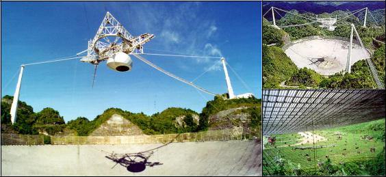
This huge radio dish nestles in a natural canyon at Arecibo, Puerto Rico. Its apparently solid surface is actually a scaffolding that hangs like a suspension bridge. It is a telescope that images the universe using radio waves rather than visible light, and it is also used to search for artificial radio signals from intelligent beings on other planets. Why does it have to be so huge? It’s not mainly a question of picking up weak signals. The dish’s sensitivity is overkill for most jobs, and for example it would have easily been able to pick up signals from a species on the other side of the galaxy that were no more intense than the ones humans themselves have transmitted out into space. (This is assuming that it was tuned to the right frequency at the right time, and that the signals came from within the limited field of view it sweeps out as the world spins.) No, the reason it has to be so big is a matter of wave optics. To make the antenna select signals from only a certain direction in space and reject those coming from other angles, it must be as large as possible compared to the wavelength of a radio wave.
5 Wave Optics
Electron microscopes can make images of individual atoms, but why will a visible-light microscope never be able to? Stereo speakers create the illusion of music that comes from a band arranged in your living room, but why doesn’t the stereo illusion work with bass notes? Why are computer chip manufacturers investing billions of dollars in equipment to etch chips with x-rays instead of visible light?
The answers to all of these questions have to do with the subject of wave optics. So far this book has discussed the interaction of light waves with matter, and its practical applications to optical devices like mirrors, but we have used the ray model of light almost exclusively. Hardly ever have we explicitly made use of the fact that light is an electromagnetic wave. We were able to get away with the simple ray model because the chunks of matter we were discussing, such as lenses and mirrors, were thousands of times larger than a wavelength of light. We now turn to phenomena and devices that can only be understood using the wave model of light.
Section 59
5.1 Diffraction
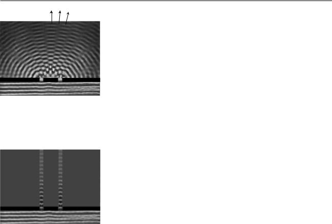
X Y Z
(a) In this view from overhead, a straight, sinusoidal water wave encounters a barrier with two gaps in it. Strong wave vibration occurs at angles X and Z, but there is none at all at angle Y.
(b) This doesn’t happen.
Figures (a) and (b) were constructed as collages of uncopyrighted photos from
PSSC College Physics. Figure (a), although essentially correct, is a little unrealistic because the waves beyond the barrier would be much weaker.
Figure (a) shows a typical problem in wave optics, enacted with water waves. It may seem surprising that we don’t get a simple pattern like figure (b), but the pattern would only be that simple if the wavelength was hundreds of times shorter than the distance between the gaps in the barrier and the widths of the gaps.
Wave optics is a broad subject, but this example will help us to pick out a reasonable set of restrictions to make things more manageable:
(1)We restrict ourselves to cases in which a wave travels through a uniform medium, encounters a certain area in which the medium has different properties, and then emerges on the other side into a second uniform region.
(2)We assume that the incoming wave is a nice tidy sine-wave pattern with wavefronts that are lines (or, in three dimensions, planes).
(3)In figure (a) we can see that the wave pattern immediately beyond the barrier is rather complex, but farther on it sorts itself out into a set of wedges separated by gaps in which the water is still. We will restrict ourselves to studying the simpler wave patterns that occur farther away, so that the main question of interest is how intense the outgoing wave is at a given angle.
The kind of phenomenon described by restriction (1) is called diffraction. Diffraction can be defined as the behavior of a wave when it encounters an obstacle or a nonuniformity in its medium. In general, diffraction causes a wave to bend around obstacles and make patterns of strong and weak waves radiating out beyond the obstacle. Understanding diffraction is the central problem of wave optics. If you understand diffraction, even the subset of diffraction problems that fall within restrictions (2) and (3), the rest of wave optics is icing on the cake.
Diffraction can be used to find the structure of an unknown diffracting object: even if the object is too small to study with ordinary imaging, it may be possible to work backward from the diffraction pattern to learn about the object. The structure of a crystal, for example, can be determined from its x-ray diffraction pattern.
Diffraction can also be a bad thing. In a telescope, for example, light waves are diffracted by all the parts of the instrument. This will cause the image of a star to appear fuzzy even when the focus has been adjusted correctly. By understanding diffraction, one can learn how a telescope must be designed in order to reduce this problem — essentially, it should have the biggest possible diameter.
There are two ways in which restriction (2) might commonly be violated. First, the light might be a mixture of wavelengths. If we simply want to observe a diffraction pattern or to use diffraction as a technique for studying the object doing the diffracting (e.g. if the object is too small to see with a microscope), then we can pass the light through a colored filter before diffracting it.
A second issue is that light from sources such as the sun or a lightbulb
60 |
Chapter 5 Wave Optics |