

B.Crowell - Optics, Vol
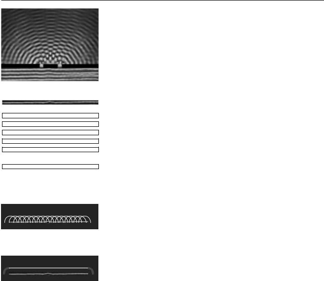
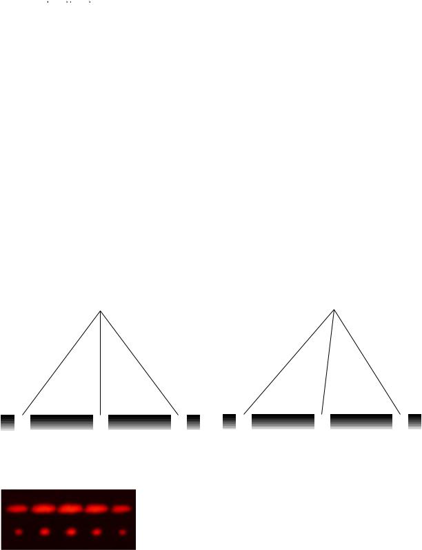
.5.pdf(c) A practical setup for observing diffraction of light.
does not consist of a nice neat plane wave, except over very small regions of space. Different parts of the wave are out of step with each other, and the wave is referred to as incoherent. One way of dealing with this is shown in figure (c). After filtering to select a certain wavelength of red light, we pass the light through a small pinhole. The region of the light that is intercepted by the pinhole is so small that one part of it is not out of step with another. Beyond the pinhole, light spreads out in a spherical wave; this is analogous to what happens when you speak into one end of a paper towel roll and the sound waves spread out in all directions from the other end. By the time the spherical wave gets to the double slit it has spread out and reduced its curvature, so that we can now think of it as a simple plane wave.
If this seems laborious, you may be relieved to know that modern technology gives us an easier way to produce a single-wavelength, coherent beam of light: the laser.
The parts of the final image on the screen in (c) are called diffraction fringes. The center of each fringe is a point of maximum brightness, and halfway between two fringes is a minimum.
Discussion Question
Why would x-rays rather than visible light be used to find the structure of a crystal? Sound waves are used to make images of fetuses in the womb. What would influence the choice of wavelength?
5.2Scaling of Diffraction
This chapter has “optics” in its title, so it is nominally about light, but we started out with an example involving water waves. Water waves are certainly easier to visualize, but is this a legitimate comparison? In fact the analogy works quite well, despite the fact that a light wave has a wavelength about a million times shorter. This is because diffraction effects scale uniformly. That is, if we enlarge or reduce the whole diffraction situation by the same factor, including both the wavelengths and the sizes of the obstacles the wave encounters, the result is still a valid solution.
This is unusually simple behavior! In the first book of this series we saw many examples of more complex scaling, such as the impossibility of bacteria the size of dogs, or the need for an elephant to eliminate heat through its ears because of its small surface-to-volume ratio, whereas a tiny shrew’s life-style centers around conserving its body heat.
Of course water waves and light waves differ in many ways, not just in scale, but the general facts you will learn about diffraction are applicable to all waves. In some ways it might have been more appropriate to insert this chapter at the end of book 3, Vibrations and Waves, but many of the important applications are to light waves, and you would probably have found these much more difficult without any background in optics.
Another way of stating the simple scaling behavior of diffraction is that the diffraction angles we get depend only on the unitless ratio λ/d, where λ is the wavelength of the wave and d is some dimension of the diffracting objects, e.g. the center-to-center spacing between the slits in figure (a). If, for instance, we scale up both λ and d by a factor of 37, the ratio λ/d will be unchanged.
Section 5.2 Scaling of Diffraction |
61 |

5.3 The Correspondence Principle
The only reason we don’t usually notice diffraction of light in everyday life is that we don’t normally deal with objects that are comparable in size to a wavelength of visible light, which is about a millionth of a meter. Does this mean that wave optics contradicts ray optics, or that wave optics sometimes gives wrong results? No. If you hold three fingers out in the sunlight and cast a shadow with them, either wave optics or ray optics can be used to predict the straightforward result: a shadow pattern with two bright lines where the light has gone through the gaps between your fingers. Wave optics is a more general theory than ray optics, so in any case where ray optics is valid, the two theories will agree. This is an example of a general idea enunciated by the physicist Niels Bohr, called the correspondence principle: when flaws in a physical theory lead to the creation of a new and more general theory, the new theory must still agree with the old theory within its more restricted area of applicability. After all, a theory is only created as a way of describing experimental observations. If the original theory had not worked in any cases at all, it would never have become accepted.
In the case of optics, the correspondence principle tells us that when λ/ d is small, both the ray and the wave model of light must give approximately the same result. Suppose you spread your fingers and cast a shadow with them using a coherent light source. The quantity λ/d is about 10 –4, so the two models will agree very closely. (To be specific, the shadows of your fingers will be outlined by a series of light and dark fringes, but the angle subtended by a fringe will be on the order of 10–4 radians, so they will be invisible and washed out by the natural fuzziness of the edges of sunshadows, caused by the finite size of the sun.)
Self-Check
What kind of wavelength would an electromagnetic wave have to have in order to diffract dramatically around your body? Does this contradict the correspondence principle?
It would have to have a wavelength on the order of centimeters or meters, the same distance scale as that of your body. These would be microwaves or radio waves. (This effect can easily be noticed when a person affects a TV’s reception by standing near the antenna.) None of this contradicts the correspondence principle, which only states that the wave model must agree with the ray model when the ray model is applicable. The ray model is not applicable here because λ/d is on the order of 1.
62 |
Chapter 5 Wave Optics |
5.4Huygens’ Principle
(a) Double-slit diffraction.
=
+
+
+
+
...
+
(b)A wavefront can be analyzed by the principle of superposition, breaking it down into many small parts.
(c)If it was by itself, each of the parts would spread out as a circular ripple.
(d)Adding up the ripples produces a new wavefront.
Returning to the example of double-slit diffraction, (a), note the strong visual impression of two overlapping sets of concentric semicircles. This is an example of Huygens’ principle, named after a Dutch physicist. (The first syllable rhymes with “boy.”) Huygens’ principle states that any wavefront can be broken down into many small side-by-side wave peaks, (b), which then spread out as circular ripples, (c), and by the principle of superposition, the result of adding up these sets of ripples must give the same result as allowing the wave to propagate forward, (d). In the case of sound or light waves, which propagate in three dimensions, the “ripples” are actually spherical rather than circular, but we can often imagine things in two dimensions for simplicity.
In double-slit diffraction the application of Huygens’ principle is visually convincing: it is as though all the sets of ripples have been blocked except for two. It is a rather surprising mathematical fact, however, that Huygens’ principle gives the right result in the case of an unobstructed linear wave, (c) and (d). A theoretically infinite number of circular wave patterns somehow conspire to add together and produce the simple linear wave motion with which we are familiar.
Since Huygens’ principle is equivalent to the principle of superposition, and superposition is a property of waves, what Huygens had created was essentially the first wave theory of light. However, he imagined light as a series of pulses, like hand claps, rather than as a sinusoidal wave.
The history is interesting. Isaac Newton loved the atomic theory of matter so much that he searched enthusiastically for evidence that light was also made of tiny particles. The paths of his light particles would correspond to rays in our description; the only significant difference between a ray model and a particle model of light would occur if one could isolate individual particles and show that light had a “graininess” to it. Newton never did this, so although he thought of his model as a particle model, it is more accurate to say he was one of the builders of the ray model.
Almost all that was known about reflection and refraction of light could be interpreted equally well in terms of a particle model or a wave model, but Newton had one reason for strongly opposing Huygens’ wave theory. Newton knew that waves exhibited diffraction, but diffraction of light is difficult to observe, so Newton believed that light did not exhibit diffraction, and therefore must not be a wave. Although Newton’s criticisms were fair enough, the debate also took on the overtones of a nationalistic dispute between England and continental Europe, fueled by English resentment over Leibnitz’s supposed plagiarism of Newton’s calculus. Newton wrote a book on optics, and his prestige and political prominence tended to discourage questioning of his model.
Thomas Young (1773-1829) was the person who finally, a hundred years later, did a careful search for wave interference effects with light and analyzed the results correctly. He observed double-slit diffraction of light as well as a variety of other diffraction effects, all of which showed that light exhibited wave interference effects, and that the wavelengths of visible light waves were extremely short. The crowning achievement was the demonstration by the experimentalist Heinrich Hertz and the theorist James Clerk
Section 5.4 Huygens’ Principle |
63 |
Maxwell that light was an electromagnetic wave. Maxwell is said to have related his discovery to his wife one starry evening and told her that she was the only person in the world who knew what starlight was.
5.5 Double-Slit Diffraction
X Y Z
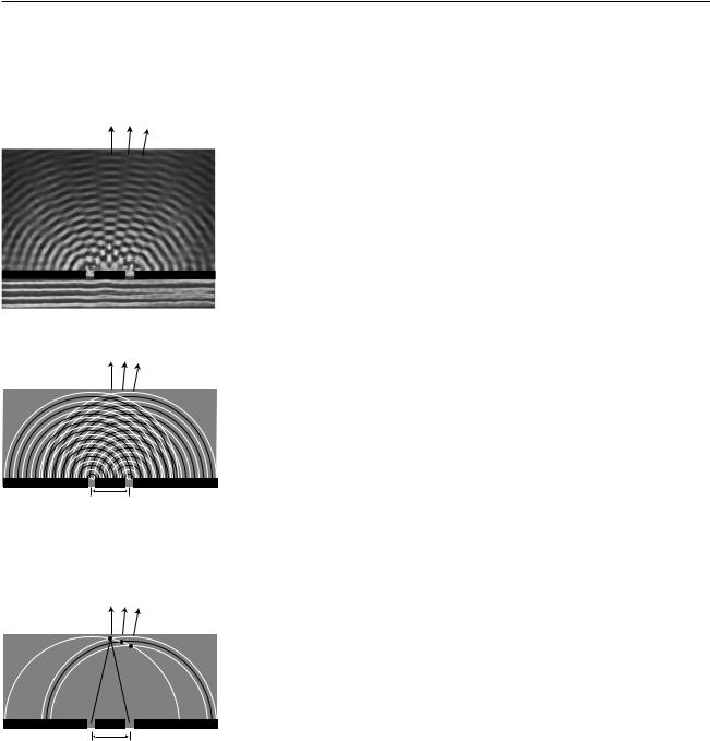
(a) Double-slit diffraction.
Let’s now analyze double-slit diffraction, (a), using Huygens’ principle. The most interesting question is how to compute the angles such as X and Z where the wave intensity is at a maximum, and the in-between angles like Y where it is minimized. Let us measure all our angles with respect to the vertical center line of the figure, which was the original direction of propagation of the wave.
If we assume that the width of the slits is small (on the order of the wavelength of the wave or less), then we can imagine only a single set of Huygens ripples spreading out from each one, (b). The only dimension of the diffracting slits that has any effect on the geometric pattern of the overlapping ripples is then the center-to-center distance, d, between the slits.
We know from our discussion of the scaling of diffraction that there must be some equation that relates an angle like θZ to the ratio λ/d,
λ / d ↔ θZ .
X Y Z
d
(b) Application of Huygens’ principle. White lines represent peaks, black lines troughs, which we can refer to as positive and negative.
X Y Z
10λ 10λ
d
(c) Because both sets of ripples have ten wavelengths to cover in order to reach the point along direction X, they will be in step when they get there.
If the equation for θZ depended on some other expression such as λ+d or λ2/d, then it would change when we scaled λ and d by the same factor, which would violate what we know about the scaling of diffraction.
Along the central maximum line, X, we always have positive waves coinciding with positive ones and negative waves coinciding with negative ones. (I have arbitrarily chosen to take a snapshot of the pattern at a moment when the waves emerging from the slit are experiencing a positive peak.) The superposition of the two sets of ripples therefore results in a doubling of the wave amplitude along this line. There is constructive interference. This is easy to explain, because by symmetry, each wave has had to travel an equal number of wavelengths to get from its slit to the center line, (c).
At the point along direction Y shown in the same figure, one wave has traveled ten wavelengths, and is therefore at a positive extreme, but the other has traveled only nine and a half wavelengths, so it at a negative extreme. There is perfect cancellation, so points along this line experience no wave motion.
But the distance traveled does not have to be equal in order to get constructive interference. At the point along direction Z, one wave has gone nine wavelengths and the other ten. They are both at a positive extreme.
64 |
Chapter 5 Wave Optics |
Self-Check
At a point half a wavelength below the point marked along direction X, carry out a similar analysis.
To summarize, we will have perfect constructive interference at any point where the distance to one slit differs from the distance to the other slit by an integer number of wavelengths. Perfect destructive interference will occur when the number of wavelengths of path length difference equals an integer plus a half.
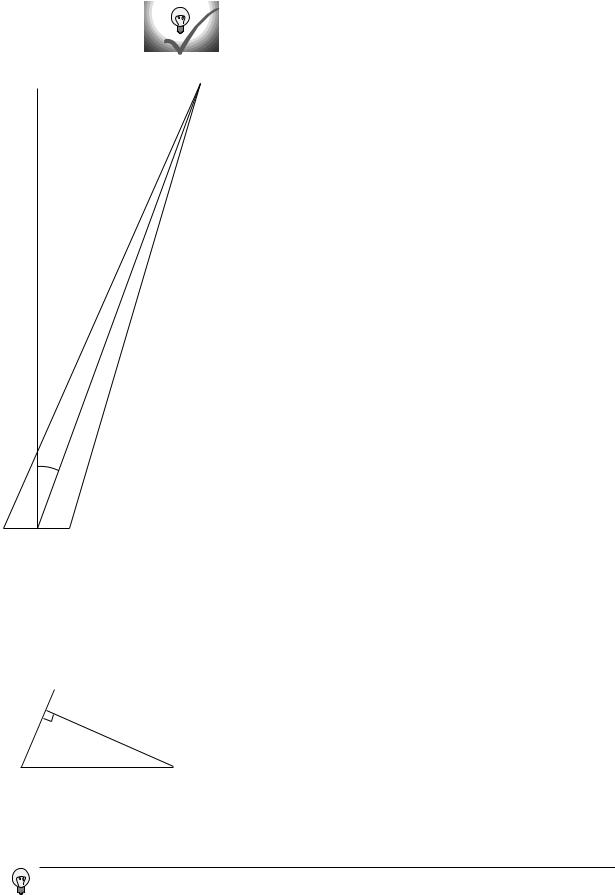
Now we are ready to find the equation that predicts the angles of the
|
maxima and minima. The waves travel different distances to get to the same |
||||
|
point in space, (d). We need to find whether the waves are in phase (in step) |
||||
|
or out of phase at this point in order to predict whether there will be |
||||
|
constructive interference, destructive interference, or something in between. |
||||
|
One of our basic assumptions in this chapter is that we will only be |
||||
|
dealing with the diffracted wave in regions very far away from the object |
||||
|
that diffracts it, so the triangle is long and skinny. Most real-world examples |
||||
|
with diffraction of light, in fact, would have triangles with even skinner |
||||
L |
proportions than this one. The two long sides are therefore very nearly |
||||
L' |
parallel, and we are justified in drawing the right triangle shown in figure |
||||
|
(e), labeling one leg of the right triangle as the difference in path length , L- |
||||
|
L’, and labeling the acute angle as θ. (In reality this angle is a tiny bit greater |
||||
|
than the one labeled θ in the previous figure.) |
||||
|
The difference in path length is related to d and θ by the equation |
||||
|
|
L – L′ |
= sin θ . |
||
θ |
|
d |
|||
|
|
|
|||
Constructive interference will result in a maximum at angles for which L–L’ |
|||||
|
|||||
|
is an integer number of wavelengths, |
||||
|
L–L’ = mλ . |
[condition for a maximum; m is an integer] |
|||
(d) The waves travel distances L1 and L2 from the two slits to get to the same point in space, at an angle θ from the center line.
L-L'
θ
d
Here m equals 0 for the central maximum, –1 for the first maximum to its left, +2 for the second maximum on the right, etc. Putting all the ingredients together, we find mλ/d=sin θ, or
λ |
= sin θ |
. [condition for a maximum; m is an integer] |
d |
m |
|
Similarly, the condition for a minimum is
λ |
= sin θ |
. [a minimum if m is an integer plus 1/2] |
d |
m |
|
That is, the minima are about halfway between the maxima.
(e) A closeup of the previous figure, showing how the path length difference L-L’ is related to d and to the angle ϕ.
At this point, both waves would have traveled nine and a half wavelengths. They would both be at a negative extreme, so there would be constructive interference.
Section 5.5 Double-Slit Diffraction |
65 |
m=0 |
1 |
1 |
As expected based on scaling, this equation relates angles to the unitless |
|
2 |
ratio λ/d. Alternatively, we could say that we have proven the scaling |
|||
|
|
|
|
|
|
|
|
|
property in the special case of double-slit diffraction. It was inevitable that |
|
|
|
|
the result would have these scaling properties, since the whole proof was |
|
|
|
|
geometric, and would have been equally valid when enlarged or reduced on |
|
|
|
|
a photocopying machine! |
d
1 m=0 2 1
d
(f) Cutting d in half doubles the angles of the diffraction fringes.
(g) Double-slit diffraction patterns of long-wavelength red light (top) and short-wavelength blue light (bottom).
Counterintuitively, this means that a diffracting object with smaller dimensions produces a bigger diffraction pattern, (f).
Example: Double-slit diffraction of blue and red light
Blue light has a shorter wavelength than red. For a given doubleslit spacing d, the smaller value of λ/d for leads to smaller values of sin θ, and therefore to a more closely spaced set of diffraction fringes, (g)
Example: The correspondence principle
Let’s also consider how the equations for double-slit diffraction relate to the correspondence principle. When the ratio λ/d is very small, we should recover the case of simple ray optics. Now if λ/ d is small, sin θ must be small as well, and the spacing between the diffraction fringes will be small as well. Although we have not proven it, the central fringe is always the brightest, and the fringes get dimmer and dimmer as we go farther from it. For small values of λ/d, the part of the diffraction pattern that is bright enough to be detectable covers only a small range of angles. This is exactly what we would expect from ray optics: the rays passing through the two slits would remain parallel, and would continue moving in the θ=0 direction. (In fact there would be images of the two separate slits on the screen, but our analysis was all in terms of angles, so we should not expect it to address the issue of whether there is structure within a set of rays that are all traveling in the θ=0 direction.)
66 |
Chapter 5 Wave Optics |

Example: Spacing of the fringes at small angles
At small angles, we can use the approximation sin θ ≈ θ , which is valid if θ is measured in radians. The equation for double-slit diffraction becomes simply
λ |
= |
θ |
, |
d |
m |
which can be solved for θ to give
θ = mλ . d
The difference in angle between successive fringes is the change in θ that results from changing m by plus or minus one,
Δθ = |
λ |
. |
|
||
|
d |
|
For example, if we write θ7 for the angle of the seventh bright fringe on one side of the central maximum and θ8 for the neighboring one, we have
θ8–θ7 = |
8λ |
– |
7λ |
|
d |
d |
|||
= |
λ |
|
, |
|
d |
|
|||
|
|
|
||
and similarly for any other neighboring pair of fringes.
Although the equation λ/d=sin θ/m is only valid for a double slit, it is can still be a guide to our thinking even if we are observing diffraction of light by a virus or a flea’s leg: it is always true that
(1)large values of λ/d lead to a broad diffraction pattern, and
(2)diffraction patterns are repetitive.
In many cases the equation looks just like λ/d = sin θ/m but with an extra numerical factor thrown in, and with d interpreted as some other dimension of the object, e.g. the diameter of a piece of wire.
Section 5.5 Double-Slit Diffraction |
67 |
5.6 |
Repetition |
|
||||||||||||
|
|
|
|
|
|
|
|
|
|
|
|
|
|
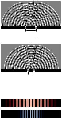
Suppose we replace a double slit with a triple slit, (a). We can think of |
|
|
|
|
|
|
|
|
|
|
|
|
|
|
this as a third repetition of the structures that were present in the double slit. |
|
|
|
|
|
|
|
|
|
|
|
|
|
|
Will this device be an improvement over the double slit for any practical |
|
|
|
|
|
|
|
|
|
|
|
|
|
|
reasons? |
|
|
|
|
|
|
|
|
|
|
|
|
|
|
|
|
|
|
|
|
|
|
|
|
|
|
|
|
|
|
|
|
|
|
|
d |
|
|
|
d |
|
|
|
|
The answer is yes, as can be shown using figures (b) and (c). For ease of |
|
|
|
|
|
|
|
|
|
|
|
|
|
|
|
(a) A triple slit. |
visualization, I have violated our usual rule of only considering points very |
|
|
|
far from the diffracting object. The scale of the drawing is such that a |
|
wavelengths is one cm. In (b), all three waves travel an integer number of |
|
wavelengths to reach the same point, so there is a bright central spot, as we |
|
would expect from our experience with the double slit. In figure (c), we |
|
show the path lengths to a new point. This point is farther from slit A by a |
|
quarter of a wavelength, and correspondingly closer to slit C. The distance |
|
from slit B has hardly changed at all. Because the paths lengths traveled |
|
from slits A and C differ from half a wavelength, there will be perfect |
|
destructive interference between these two waves. There is still some |
|
uncanceled wave intensity because of slit B, but the amplitude will be three |
|
times less than in figure (b), resulting in a factor of 9 decrease in brightness. |
|
Thus, by moving off to the right a little, we have gone from the bright |
|
central maximum to a point that is quite dark. |
|
Now let’s compare with what would have happened if slit C had been |
|
covered, creating a plain old double slit. The waves coming from slits A and |
|
B would have been out of phase by 0.23 wavelengths, but this would not |
|
have caused very severe interference. The point in figure (c) would have |
|
been quite brightly lit up. |
|
To summarize, we have found that adding a third slit narrows down the |
|
central fringe dramatically. The same is true for all the other fringes as well, |
5λ |
|
5λ |
5.25 λ |
4.75 λ |
|
4λ |
4.02 |
λ |
|||
|
|
||||
|
|
|
A B C A B C
(b) There is a bright central maximum. |
(c) At this point just off the central maximum, the path lengths |
|
|
|
traveled by the three waves have changed. |
(d) A double-slit diffraction pattern (top), and a pattern made by five slits (bottom).. (Photo by the author.)
68 |
Chapter 5 Wave Optics |
and since the same amount of energy is concentrated in narrower diffraction fringes, each fringe is brighter and easier to see, (d).
This is an example of a more general fact about diffraction: if some feature of the diffracting object is repeated, the locations of the maxima and minima are unchanged, but they become narrower.
Taking this reasoning to its logical conclusion, a diffracting object with thousands of slits would produce extremely narrow fringes. Such an object is called a diffraction grating.
5.7Single-Slit Diffraction
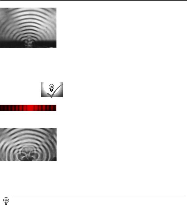
(a) Single-slit diffraction of water waves. (PSSC Physics.)
If we use only a single slit, is there diffraction? If the slit is very narrow compared to a wavelength of light, then we can approximate its behavior by using only a single set of Huygens ripples. There are no other sets of ripples to add to it, so there are no constructive or destructive interference effects, and no maxima or minima. The result will be a uniform spherical wave of light spreading out in all directions, like what we would expect from a tiny lightbulb. We could call this a diffraction pattern, but it is a completely featureless one, and it could not be used, for instance, to determine the wavelength of the light, as other diffraction patterns could.
All of this, however, assumes that the slit is narrow compared to a wavelength of light. If, on the other hand, the slit is broader, there will indeed be interference among the sets of ripples spreading out from various points along the opening. Figure (a) shows an example with water waves, and figure (b) with light.
Self-Check
(b) Single-slit diffraction of red light. Note the double width of the central maximum. (Photo by the author.)
(c) A pretty good simulation of the single-slit pattern of figure (a), made by using three motors to produce overlapping ripples from three neighboring points in the water. (PSSC Physics)
How does the wavelength of the waves compare with the width of the slit in figure (a)?
We will not go into the details of the analysis of single-slit diffraction, but let us see how its properties can be related to the general things we’ve learned about diffraction. We know based on scaling arguments that the angular sizes of features in the diffraction pattern must be related to the wavelength and the width, a, of the slit by some relationship of the form
λa ↔ θ .
This is indeed true, and for instance the angle between the maximum of the central fringe and the maximum of the next fringe on one side equals 1.5λ/
a. Scaling arguments will never produce factors such as the 1.5, but they tell us that the answer must involve λ/a, so all the familiar qualitative facts are true. For instance, shorter-wavelength light will produce a more closely spaced diffraction pattern.
Judging by the distance from one bright wave crest to the next, the wavelength appears to be about 2/3 or 3/4 as great as the width of the slit.
Section 5.7 Single-Slit Diffraction |
69 |

An important scientific example of single-slit diffraction is in telescopes. Images of individual stars, as in the figure above, are a good way to examine diffraction effects, because all stars except the sun are so far away that no telescope, even at the highest magnification, can image their disks or surface features. Thus any features of a star’s image must be due purely to optical effects such as diffraction. A prominent cross appears around the brightest star, and dimmer ones surround the dimmer stars. Something like this is seen in most telescope photos, and indicates that inside the tube of the telescope there were two perpendicular struts or supports. Light diffracted around these struts. You might think that diffraction could be eliminated entirely by getting rid of all obstructions in the tube, but the circles around the stars are diffraction effects arising from single-slit diffraction at the mouth of the telescope’s tube! (Actually we have not even talked about diffraction through a circular slit, but the idea is the same.) Since the angular sizes of the diffracted images depend on λ/a, the only way to improve the resolution of the images is to increase the diameter, a, of the tube. This is one of the main reasons (in addition to light-gathering power) why the best telescopes must be very large in diameter.
Self-Check
What would this imply about radio telescopes as compared with visible-light telescopes?
Discussion Question
Why is it optically impossible for bacteria to evolve eyes that use visible light to form images?
Since the wavelengths of radio waves are thousands of times longer, diffraction causes the resolution of a radio telescope to be thousands of times worse, all other things being equal.
70 |
Chapter 5 Wave Optics |