

B.Crowell - Optics, Vol
.5.pdfso do light rays. This type of symmetry is called time-reversal symmetry.
Typically, time-reversal symmetry is a characteristic of any process that does not involve heat. For instance, the planets do not experience any friction as they travel through empty space, so there is no frictional heating. We should thus expect the time-reversed versions of their orbits to obey the laws of physics, which they do. In contrast, a book sliding across a table does generate heat from friction as it slows down, and it is therefore not surprising that this type of motion does not appear to obey time-reversal symmetry. A book lying still on a flat table is never observed to spontaneously start sliding, sucking up heat energy and transforming it into kinetic energy.
Similarly, the only situation we’ve observed so far where light does not obey time-reversal symmetry is absorption, which involves heat. Your skin absorbs visible light from the sun and heats up, but we never observe people’s skin to glow, converting heat energy into visible light. People’s skin does glow in infrared light, but that doesn’t mean the situation is symmetric. Even if you absorb infrared, you don’t emit visible light, because your skin isn’t hot enough to glow in the visible spectrum.
Discussion Questions
A. If a light ray has a velocity vector with components cx and cy, what will
happen when it is reflected from a surface that lies along the y axis? Make
sure your answer does not imply a change in the ray’s speed.
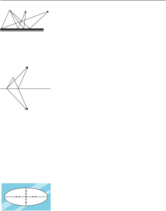
B. Generalizing your reasoning from discussion question B, what will happen to the velocity components of a light ray that hits a corner, as shown in the figure, and undergoes two reflections?
C. Three pieces of sheet metal arranged perpendicularly as shown in the figure form what is known as a radar corner. Let’s assume that the radar corner is large compared to the wavelength of the radar waves, so that the ray model makes sense. If the radar corner is bathed in radar rays, at least some of them will undergo three reflections. Making a further generalization of your reasoning from the two preceding discussion questions, what will happen to the three velocity components of such a ray? What would the radar corner be useful for?
Discussion question B.
Discussion question C.
Section 1.4 Geometry of Specular Reflection |
21 |
1.5* The Principle of Least Time for Reflection
A B
|
We had to choose between an unwieldy explanation of reflection at the |
C |
atomic level and a simpler geometric description that was not as fundamen- |
|
tal. There is a third approach to describing the interaction of light and |
|
matter which is very deep and beautiful. Emphasized by the twentieth- |
|
century physicist Richard Feynman, it is called the principle of least time, |
|
or Fermat’s principle. |
(a) The solid lines are physically possible paths for ight rays traveling from A to B and from A to C. They obey the principle of least time. The dashed lines do not obey the principle of least time, and are not physically possible.
B
A
P Q
C
(b) Paths AQB and APB are two conceivable paths that a ray could travel to get from A to B with one reflection, but only AQB is physically possible. We wish to prove that path AQB, with equal angles of incidence and reflection, is shorter than any other path, such as APB. The trick is to contruct a third point, C, lying as far below the surface as B lies above it. Then path AQC is a straight line whose length is the same as AQB, and path APC has the same length as path APB. Since AQC is straight, it must be shorter than any other path such as APC that connects A and C, and therefore AQB must be shorter than any path such as APB.
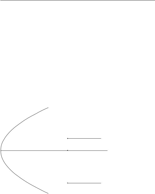
(c) Light is emitted at the center of an elliptical mirror. There are four physically possible paths by which a ray can be reflected and return to the center.
Let’s start with the motion of light that is not interacting with matter at all. In a vacuum, a light ray moves in a straight line. This can be rephrased as follows: of all the conceivable paths light could follow from P to Q, the only one that is physically possible is the path that takes the least time.
What about reflection? If light is going to go from one point to another, being reflected on the way, the quickest path is indeed the one with equal angles of incidence and reflection. If the starting and ending points are equally far from the reflecting surface, (a), it’s not hard to convince yourself that this is true, just based on symmetry. There is also a tricky and simple proof, shown in the bottom panel of the figure, for the more general case where the points are at different distances from the surface.
Not only does the principle of least time work for light in a vacuum and light undergoing reflection, we will also see in a later chapter that it works for the bending of light when it passes from one medium into another.
Although it is beautiful that the entire ray model of light can be reduced to one simple rule, the principle of least time, it may seem a little spooky to speak as if the ray of light is intelligent, and has carefully planned ahead to find the shortest route to its destination. How does it know in advance where it’s going? What if we moved the mirror while the light was en route, so conditions along its planned path were not what it “expected”? The answer is that the principle of least time is really a shortcut for finding certain results of the wave model of light, which is the topic of the last chapter of this book.
There are a couple of subtle points about the principle of least time. First, the path does not have to be the quickest of all possible paths; it only needs to be quicker than any path that differs infinitesimally from it. In figure (b), for instance, light could get from A to B either by the reflected path AQB or simply by going straight from A to B. Although AQB is not the shortest possible path, it cannot be shortened by changing it infinitesimally, e.g. by moving Q a little to the right or left. On the other hand, path APB is physically impossible, because it is possible to improve on it by moving point P infinitesimally to the right.
It should also be noted that it’s a misnomer to call this the principle of least time. In figure (c), for example, the four physically possible paths by which a ray can return to the center consist of two shortest-time paths and two longest-time paths. Strictly speaking, we should refer to the principle of least or greatest time, but most physicists omit the niceties, and assume that other physicists understand that both maxima and minima are possible.
22 |
Chapter 1 The Ray Model of Light |

Summary
Selected Vocabulary |
|
absorption ......................... |
what happens when light hits matter and gives up some of its energy |
reflection ........................... |
what happens when light hits matter and bounces off, retaining at least |
|
some of its energy |
specular reflection .............. |
reflection from a smooth surface, in which the light ray leaves at the same |
|
angle at which it came in |
diffuse reflection ................ |
reflection from a rough surface, in which a single ray of light is divided up |
|
into many weaker reflected rays going in many directions |
normal .............................. |
the line perpendicular to a surface at a given point |
Notation |
|
c ........................................ |
the speed of light |
Summary |
|
We can understand many phenomena involving light without having to use sophisticated models such as the wave model or the particle model. Instead, we simply describe light according to the path it takes, which we call a ray. The ray model of light is useful when light is interacting with material objects that are much larger than a wavelength of light. Since a wavelength of visible light is so short compared to the human scale of existence, the ray model is useful in many practical cases.
We see things because light comes from them to our eyes. Objects that glow may send light directly to our eyes, but we see an object that doesn’t glow via light from another source that has been reflected by the object.
Many of the interactions of light and matter can be understood by considering what happens when light reaches the boundary between two different substances. In this situation, part of the light is reflected (bounces back) and part passes on into the new medium. This is not surprising — it is typical behavior for a wave, and light is a wave. Light energy can also be absorbed by matter, i.e. converted into heat.
A smooth surface produces specular reflection, in which the reflected ray exits at the same angle with respect to the normal as that of the incoming ray. A rough surface gives diffuse reflection, where a single ray of light is divided up into many weaker reflected rays going in many directions.
Summary 23
Homework Problems
1. Draw a ray diagram showing why a small light source (a candle, say) produces sharper shadows than a large one (e.g. a long fluorescent bulb).
2. A Global Positioning System (GPS) receiver is a device that lets you figure out where you are by exchanging radio signals with satellites. It works by measuring the round-trip time for the signals, which is related to the distance between you and the satellite. By finding the ranges to several different satellites in this way, it can pin down your location in three dimensions to within a few meters. How accurate does the measurement of the time delay have to be to determine your position to this accuracy?
3. Estimate the frequency of an electromagnetic wave whose wavelength is similar in size to an atom (about a nm). Referring back to book 4, in what part of the electromagnetic spectrum would such a wave lie (infrared, gamma-rays,...)?
4. The Stealth bomber is designed with flat, smooth surfaces. Why would this make it difficult to detect via radar?
5. The large figure shows a curved (parabolic) mirror, with three parallel light rays coming toward it. One ray is approaching along the mirror’s center line. (a) Trace the drawing accurately, and continue the light rays until they are about to undergo their second reflection. To determine the angles accurately, you’ll want to draw in the normal at the point where the ray hits the mirror. What do you notice? (b) Make up an example of a practical use for this device. (c) How could you use this mirror with a small lightbulb to produce a parallel beam of light rays going off to the right?
Problem 5.
S |
A solution is given in the back of the book. |
↔ A difficult problem. |
|
A computerized answer check is available. |
ò A problem that requires calculus. |
24 |
Chapter 1 The Ray Model of Light |
2 Images by Reflection, Part I
Infants are always fascinated by the antics of the Baby in the Mirror. Now if you want to know something about mirror images that most people don’t understand, try this. First bring this page and closer to your eyes, until you can no longer focus on it without straining. Then go in the bathroom and see how close you can get your face to the surface of the mirror before you can no longer easily focus on the image of your own eyes. You will find that the shortest comfortable eye-mirror distance is much less than the shortest comfortable eye-paper distance. This demonstrates that the image of your face in the mirror acts as if it had depth and existed in the space behind the mirror. If the image was like a flat picture in a book, then you wouldn’t be able to focus on it from such a short distance.
In this chapter we will study the images formed by flat and curved mirrors on a qualitative, conceptual basis. Although this type of image is not as commonly encountered in everyday life as images formed by lenses, images formed by reflection are simpler to understand, so we discuss them first. In chapter 3 we will turn to a more mathematical treatment of images made by reflection. Surprisingly, the same equations can also be applied to lenses, which are the topic of chapter 4.
25
2.1 A Virtual Image
ca
b 
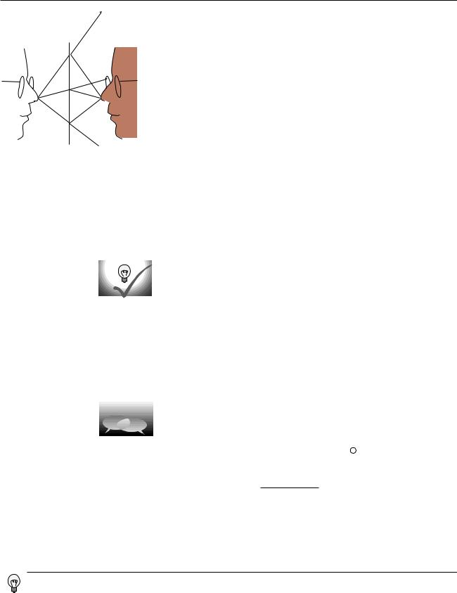
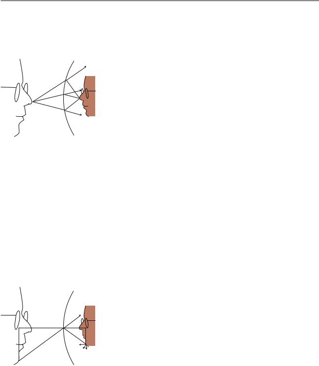
(a)An image formed by a mirror.
We can understand a mirror image using a ray diagram. The figure shows several light rays, a, that originated by diffuse reflection at the person’s nose. They bounce off the mirror, producing new rays, b. To anyone whose eye is in the right position to get one of these rays, they appear to have come from a behind the mirror, c, where they would have originated from a single point. This point is where the tip of the imageperson’s nose appears to be. A similar analysis applies to every other point on the person’s face, so it looks as though there was an entire face behind the mirror. The customary way of describing the situation requires some explanation:
Customary description in physics: There is an image of the face behind the mirror.
Translation: The pattern of rays coming from the mirror is exactly the same as it would be if there was a face behind the mirror. Nothing is really behind the mirror.
This is referred to as a virtual image, because the rays do not actually cross at the point behind the mirror. They only appear to have originated there.
Self-Check
Imagine that the person in figure (a) moves his face down quite a bit — a
couple of feet in real life, or a few inches on this scale drawing. Draw a new ray diagram. Will there still be an image? If so, where is it visible from?
The geometry of specular reflection tells us that rays a and b are at equal angles to the normal (the imaginary perpendicular line piercing the mirror at the point of reflection). This means that ray b’s imaginary continuation, c, forms the same angle with the mirror as ray a. Since each ray of type c forms the same angles with the mirror as its partner of type a, we see that the distance of the image from the mirror is the same as the actual face from the mirror, and lies directly across from it. The image therefore appears to be the same size as the actual face.
Discussion Question
The figure shows an object that is off to one side of a mirror. Draw a ray diagram. Is an image formed? If so, where is it, and from which directions would it be visible?
You should have found from your ray diagram that an image is still formed, and it has simply moved down the same distance as the real face. However, this new image would only be visible from high up, and the person can no longer see his own image. If you couldn’t draw a ray diagram that seemed to result in an image, the problem was probably that you didn’t choose any rays that happened to go away from the face in the right direction to hit the mirror.
26 |
Chapter 2 Images by Reflection, Part I |
2.2Curved Mirrors
c a
b
(b) An image formed by a curved mirror.
B |
C |
D |
|
|
|
|
|
E |
A |
|
|
(c) The image is magnified by the same factor in depth and in its other dimensions.
An image in a flat mirror is a pretechnological example: even animals can look at their reflections in a calm pond. We now pass to our first nontrivial example of the manipulation of an image by technology: an image in a curved mirror. Before we dive in, let’s consider why this is an important example. If it was just a question of memorizing a bunch of facts about curved mirrors, then you would rightly rebel against an effort to spoil the beauty of your liberally educated brain by force-feeding you technological trivia. The reason this is an important example is not that curved mirrors are so important in and of themselves, but that the results we derive for curved bowl-shaped mirrors turn out to be true for a large class of other optical devices, including mirrors that bulge outward rather than inward, and lenses as well. A microscope or a telescope is simply a combination of lenses or mirrors or both. What you’re really learning about here is the basic building block of all optical devices from movie projectors to octopus eyes.
Because the mirror in figure (b) is curved, it bends the rays back closer together than a flat mirror would: we describe it as inbending. Note that the term refers to what it does to the light rays, not to the physical shape of the mirror’s surface . (The surface itself would be described as concave. The term is not all that hard to remember, because the hollowed-out interior of the mirror is like a cave.) It is surprising but true that all the rays like c really do converge on a point, forming a good image. We will not prove this fact, but it is true for any mirror whose curvature is gentle enough and that is symmetric with respect to rotation about the perpendicular line passing through its center (not asymmetric like a potato chip). The old-fashioned method of making mirrors and lenses is by grinding them in grit by hand, and this automatically tends to produce an almost perfect spherical surface.
Bending a ray like b inward implies bending its imaginary continuation c outward, in the same way that raising one end of a seesaw causes the other end to go down. The image therefore forms deeper behind the mirror. This doesn’t just show that there is extra distance between the image-nose and the mirror; it also implies that the image itself is bigger from front to back. It has been magnified in the front-to-back direction.
It is easy to prove that the same magnification also applies to the image’s other dimensions. Consider a point like E in figure (c). The trick is that out of all the rays diffusely reflected by E, we pick the one that happens to head for the mirror’s center, C. The equal-angle property of specular reflection plus a little straightforward geometry easily leads us to the conclusion that triangles ABC and CDE are the same shape, with ABC being simply a scaled-up version of CDE. The magnification of depth equals the ratio BC/ CD, and the up-down magnification is AB/DE. A repetition of the same proof shows that the magnification in the third dimension (out of the page) is also the same. This means that the image-head is simply a larger version of the real one, without any distortion. The scaling factor is called the magnification, M. The image in the figure is magnified by a factor M=1.9.
Note that we did not explicitly specify whether the mirror was a sphere, a paraboloid, or some other shape. However, we assumed that a focused image would be formed, which would not necessarily be true, for instance, for a mirror that was asymmetric or very deeply curved.
Section 2.2 Curved Mirrors |
27 |
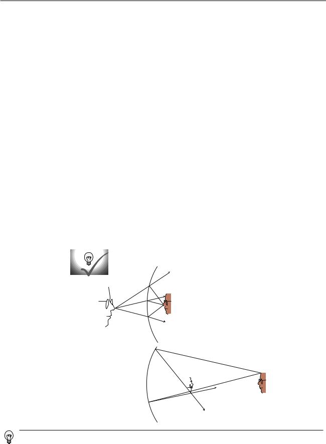
2.3 A Real Image
If we start by placing an object very close to the mirror, (d), and then move it farther and farther away, the image at first behaves as we would expect from our everyday experience with flat mirrors, receding deeper and deeper behind the mirror. At a certain point, however, a dramatic change occurs. When the object is more than a certain distance from the mirror, (e), the image appears upside-down and in front of the mirror.
Here’s what’s happened. The mirror bends light rays inward, but when the object is very close to it, as in (d), the rays coming from a given point on the object are too strongly diverging (spreading) for the mirror to bring them back together. On reflection, the rays are still diverging, just not as strongly diverging. But when the object is sufficiently far away, (e), the mirror is only intercepting the rays that came out in a narrow cone, and it is able to bend these enough so that they will reconverge.
Note that the rays shown in the figure, which both originated at the same point on the object, reunite when they cross. The point where they cross is the image of the point on the original object. This type of image is called a real image, in contradistinction to the virtual images we’ve studied before. The use of the word “real” is perhaps unfortunate. It sounds as though we are saying the image was an actual material object, which of course it is not.
The distinction between a real image and a virtual image is an important one, because a real image can projected onto a screen or photographic film. If a piece of paper is inserted in figure (e) at the location of the image, the image will be visible to someone looking at the paper from the left. Your eye uses a lens to make a real image on the retina.
Self-Check
Sketch another copy of the face in figure (e), even farther from the mirror, and draw a ray diagram. What has happened to the location of the image?
(d) A virtual image.
(e) A real image.
Increasing the distance from the face to the mirror has decreased the distance from the image to the mirror. This is the opposite of what happened with the virtual image.
28 |
Chapter 2 Images by Reflection, Part I |
2.4Images of Images
I
I′
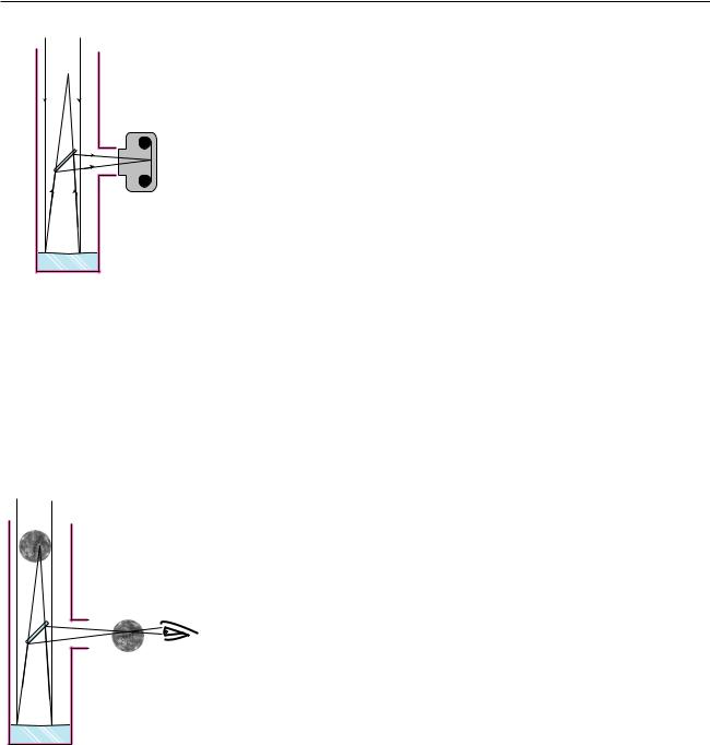
(f) A Newtonian telescope being used with a camera.
I
I′
(g) A Newtonian telescope being used for visual rather than photographic observing. In real life, an eyepiece lens is normally used for additional magnification, but this simpler setup will also work.
If you are wearing glasses right now, then the light rays from the page are being manipulated first by your glasses and then by the lens of your eye. You might think that it would be extremely difficult to analyze this, but in fact it is quite easy. In any series of optical elements (mirrors or lenses or both), each element works on the rays furnished by the previous element in exactly the same manner as if the image formed by the previous element was an actual object.
Figure (f) shows an example involving only mirrors. The Newtonian telescope, invented by Isaac Newton, consists of a large curved mirror, plus a second, flat mirror that brings the light out of the tube. (In very large telescopes, there may be enough room to put a camera or even a person inside the tube, in which case the second mirror is not needed.) The tube of the telescope is not vital; it is mainly a structural element, although it can also be helpful for blocking out stray light. The lens has been removed from the front of the camera body, and is not needed for this setup. Note that the two sample rays have been drawn parallel, because an astronomical telescope is used for viewing objects that are extremely far away. These two “parallel” lines actually meet at a certain point, say a crater on the moon, so they can’t actually be perfectly parallel, but they are parallel for all practical purposes since we would have to follow them upward for a quarter of a million miles to get to the point where they intersect.
The large curved mirror by itself would form an image I, but the small flat mirror creates an image of the image, I′. The relationship between I and I′ is exactly the same as it would be if I was an actual object rather than an image: I and I′ are at equal distances from the plane of the mirror, and the line between them is perpendicular to the plane of the mirror.
One surprising wrinkle is that whereas a flat mirror used by itself forms a virtual image of an object that is real, here the mirror is forming a real image of virtual image I. This shows how pointless it would be to try to memorize lists of facts about what kinds of images are formed by various optical elements under various circumstances. You are better off simply drawing a ray diagram.
Although the main point here was to give an example of an image of an image, this is also an interesting case where we need to make the distinction between magnification and angular magnification. If you are looking at the moon through this telescope, then the images I and I′ are much smaller than the actual moon. Otherwise, for example, image I would not fit inside the telescope! However, these images are very close to your eye compared to the actual moon. The small size of the image has been more than compensated for by the shorter distance. The important thing here is the amount of angle within your field of view that the image covers, and it is this angle that has been increased. The factor by which it is increased is called the angular magnification, Ma.
Section 2.4 Images of Images |
29 |
Discussion Questions
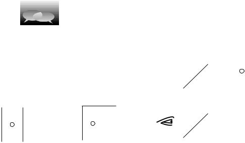
A. Describe the images that will be formed of you if you stand between two
parallel mirrors.
B. Locate the images formed by two perpendicular mirrors, as in the figure. What happens if the mirrors are not perfectly perpendicular?
C. Locate the images formed by the periscope.
Discussion question A. |
Discussion question B. |
Discussion question C. |
30 |
Chapter 2 Images by Reflection, Part I |