

Cisco Secure VPN Exam Certification Guide - Cisco press
.pdf268Chapter 6: Configuring the Cisco VPN Client Firewall Feature
•DHCP requests—Dynamic Host Configuration Protocol (DHCP) requests are sent from the client on one port to the DHCP server and received on a different port.
•ESP—Encapsulating Security Payload (ESP) is VPN data that are allowed from the secure gateway because ESP rules are always packet filters, as opposed to session-based filters.
Turning off the Always On option allows the user to have a secure VPN connection to the headend network while still having nonsecured connections to other networks, such as the Internet. This merging of secured and nonsecured traffic on the same wire is called split tunneling. The Stateful Firewall (Always On) feature provides protection for nonsecured traffic when split tunneling is in use.
Cisco Integrated Client
The VPN Client used on the Windows platforms includes a stateful firewall that is transparent to the user. Designed by Zone Labs, this firewall is called the Cisco Integrated Client (CIC). Although the Always On option of the VPN Client allows the user to choose whether to have basic firewall protection in place, the CIC can still be controlled by the concentrator using the Central Protection Policy (CPP). CPP allows the VPN concentrator to define rules for use during split-tunnel operation. Because the Tunnel Everything option already blocks all nontunneled traffic, CPP is not used in this mode.
The Zone Labs Integrity Server, commonly refereed to as IS, is a stand-alone server that communicates with the VPN concentrator to maintain policies for the remote PCs. The IS also ensures policy enforcement by communicating with the concentrator to allow or drop connections, exchange session and user information, and report the status of connections.
Centralized Protection Policy
CPP, which is also known as a push policy because it is pushed from the concentrator down to the client, allows you to define additional rules to allow or deny Internet traffic while the client is connected to the concentrator.
During the VPN connection negotiation, the concentrator sends a predefined policy to the VPN Client. The client then passes this policy to the CIC, which in turn enforces the policy. If the Always On option has been chosen on the client, more restrictive rules can be used regarding Internet traffic while the tunnel is established.
CPP can use a number of firewalls to enforce these rules, including CIC, Zone Alarm, and Zone AlarmPro. CPP allows finer tuning of the firewall than the Stateful Firewall feature because you can allow or deny specific ports and protocols.
Configuring Firewall Filter Rules 269
The Are You There Feature
An alternative to using the CPP method of defining policies on the personal firewall is where the VPN Client polls a firewall installed on the client PC every 30 seconds. This process is called Are You There (AYT). If the firewall does not answer these polls, the VPN Client drops the tunnel. Using this method, the VPN Client does not enforce a policy but rather ensures that a software firewall on the PC is running.
AYT is usable with BlackICE, Zone Alarm, or Zone AlarmPro. The only messages passed between the concentrator and the firewall are these AYT polls.
Configuring Firewall Filter Rules
24 Customizing firewall policy
Before you can use filter rules from the concentrator, you must configure those rules. Although the concentrator’s default configuration comes with some rules, these are not meant for production networks. The default rules are too open for a truly secure environment because they were designed merely to facilitate the building of rules for your individual network. Rules, which are specifications that allow or deny specific types of traffic, can be applied to either an interface or a VPN group. This section discusses how to build rules and filters for use with the VPN concentrator.
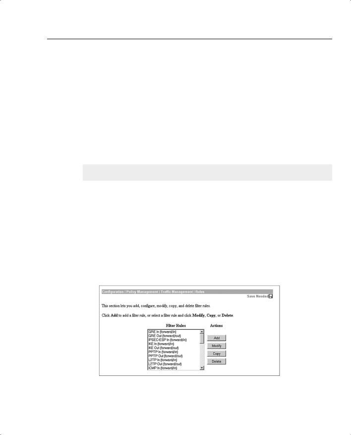
Rules are configured from the Configuration | Policy Management | Traffic Management | Rules screen, as shown in Figure 6-2.
Figure 6-2 The Configuration | Policy Management | Traffic Management | Rules Screen

270 Chapter 6: Configuring the Cisco VPN Client Firewall Feature
On this screen, you can add, modify, copy, or delete rules. The list shown consists of the default rules and those rules that the administrator has added, minus the deleted rules. Notice that each of these rules has text inside parentheses. The text within the parentheses describes the action and direction. The meaning of this action and direction text is discussed in the section describing the creation of a rule, “Name, Direction, and Action.”
The default rules are listed in Table 6-3. For the default rules, the action is almost always forward and the source address is always Use IP Address/Wildcard mask, which is set to any address (0.0.0.0 255.255.255.255). The destination IP address is always Use IP Address/Wildcard mask, which is set to any address (0.0.0.0/255.255.255.255). The exceptions to these rules are with Virtual Router Redundancy Protocol (VRRP) In and VRRP Out, which use the Internet Assigned Numbers Authority (IANA)–assigned multicast IP address of 224.0.0.18/0.0.0.0.
Table 6-3 Default Rules
|
|
|
|
TCP/UDP |
TCP/UDP |
ICMP |
|
|
|
TCP |
Source |
Connection |
Packet |
Rule |
Direction |
Protocol |
Connection |
Port |
Port |
Type |
|
|
|
|
|
|
|
Any In |
Inbound |
Any |
Don’t care |
0–65535 |
0–65,535 |
0–255 |
|
|
|
|
|
|
|
Any Out |
Outbound |
Any |
Don’t care |
0–65635 |
0–65,635 |
0–255 |
|
|
|
|
|
|
|
Certificate |
Inbound |
TCP |
Don’t care |
389 |
0–65,535 |
N/A |
Revocation List |
|
|
|
|
|
|
(CRL) checking |
|
|
|
|
|
|
over LDAP In |
|
|
|
|
|
|
|
|
|
|
|
|
|
CRL checking |
Outbound |
TCP |
Don’t care |
0–65535 |
389 |
N/A |
over LDAP Out |
|
|
|
|
|
|
|
|
|
|
|
|
|
Generic Routing |
Inbound |
GRE |
N/A |
N/A |
N/A |
N/A |
Encapsulation |
|
|
|
|
|
|
(GRE) In |
|
|
|
|
|
|
|
|
|
|
|
|
|
GRE Out |
Outbound |
GRE |
N/A |
N/A |
N/A |
N/A |
|
|
|
|
|
|
|
ICMP In |
Inbound |
ICMP |
N/A |
N/A |
N/A |
0–18 |
|
|
|
|
|
|
|
ICMP Out |
Outbound |
ICMP |
N/A |
N/A |
N/A |
0–18 |
|
|
|
|
|
|
|
IKE In |
Inbound |
UDP |
N/A |
0–65,535 |
500 |
N/A |
|
|
|
|
|
|
|
IKE Out |
Outbound |
UDP |
N/A |
500 |
65,535 |
N/A |
|
|
|
|
|
|
|
Incoming HTTP |
Inbound |
TCP |
Don’t care |
0–65,535 |
80 |
N/A |
In |
|
|
|
|
|
|
|
|
|
|
|
|
|
Incoming HTTP |
Outbound |
TCP |
Don’t care |
80 |
65,535 |
N/A |
Out |
|
|
|
|
|
|
|
|
|
|
|
|
|
Incoming |
Inbound |
TCP |
Don’t care |
0–65,535 |
443 |
N/A |
HTTPS In |
|
|
|
|
|
|
|
|
|
|
|
|
|

Configuring Firewall Filter Rules 271
Table 6-3 Default Rules (Continued)
|
|
|
|
TCP/UDP |
TCP/UDP |
ICMP |
|
|
|
TCP |
Source |
Connection |
Packet |
Rule |
Direction |
Protocol |
Connection |
Port |
Port |
Type |
|
|
|
|
|
|
|
Incoming |
Outbound |
TCP |
Don’t care |
443 |
0–65,535 |
N/A |
HTTPS Out |
|
|
|
|
|
|
|
|
|
|
|
|
|
IPSec-ESP In |
Inbound |
ESP |
N/A |
N/A |
N/A |
N/A |
|
|
|
|
|
|
|
L2TP In |
Inbound |
UDP |
N/A |
0–65,535 |
1701 |
N/A |
|
|
|
|
|
|
|
L2TP Out |
Outbound |
UDP |
N/A |
1701 |
0–65,535 |
N/A |
|
|
|
|
|
|
|
LDAP In |
Inbound |
TCP |
Don’t care |
0–65,535 |
389 |
N/A |
|
|
|
|
|
|
|
LDAP Out |
Outbound |
TCP |
Don’t care |
389 |
0–65,535 |
N/A |
|
|
|
|
|
|
|
OSPF In |
Inbound |
OSPF |
N/A |
N/A |
N/A |
N/A |
|
|
|
|
|
|
|
OSPF Out |
Outbound |
OSPF |
N/A |
N/A |
N/A |
N/A |
|
|
|
|
|
|
|
Outgoing HTTP |
Inbound |
TCP |
Don’t care |
80 |
0–65,535 |
N/A |
In |
|
|
|
|
|
|
|
|
|
|
|
|
|
Outgoing HTTP |
Outbound |
TCP |
Don’t care |
0–65,535 |
80 |
N/A |
Out |
|
|
|
|
|
|
|
|
|
|
|
|
|
Outgoing HTTPS |
Inbound |
TCP |
Don’t care |
443 |
0–65,535 |
N/A |
In |
|
|
|
|
|
|
|
|
|
|
|
|
|
Outgoing HTTPS |
Outbound |
TCP |
Don’t care |
0–65,535 |
443 |
N/A |
Out |
|
|
|
|
|
|
|
|
|
|
|
|
|
PPTP In |
Inbound |
TCP |
Don’t care |
0–65,535 |
1723 |
N/A |
|
|
|
|
|
|
|
PPTP Out |
Outbound |
TCP |
Don’t care |
1723 |
0–65,535 |
N/A |
|
|
|
|
|
|
|
RIP In |
Inbound |
UDP |
N/A |
520 |
520 |
N/A |
|
|
|
|
|
|
|
RIP Out |
Outbound |
UDP |
N/A |
520 |
520 |
N/A |
|
|
|
|
|
|
|
Secure Shell |
Inbound |
TCP |
Don’t care |
0–65,535 |
22 |
N/A |
(SSH) In |
|
|
|
|
|
|
|
|
|
|
|
|
|
SSH Out |
Outbound |
TCP |
Don’t care |
22 |
0–65,535 |
N/A |
|
|
|
|
|
|
|
Telnet/SSL In |
Inbound |
TCP |
Don’t care |
0–65,535 |
992 |
N/A |
|
|
|
|
|
|
|
Telnet/SSL Out |
Outbound |
TCP |
Don’t care |
992 |
0–65,535 |
N/A |
|
|
|
|
|
|
|
Virtual Cluster |
Inbound |
UDP |
N/A |
0–65,535 |
9023 |
N/A |
Agent (VCA) In |
|
|
|
|
|
|
|
|
|
|
|
|
|
VCA Out |
Outbound |
UDP |
N/A |
9023 |
0–65,535 |
N/A |
|
|
|
|
|
|
|
continues

272 Chapter 6: Configuring the Cisco VPN Client Firewall Feature
Table 6-3 Default Rules (Continued)
|
|
|
|
TCP/UDP |
TCP/UDP |
ICMP |
|
|
|
TCP |
Source |
Connection |
Packet |
Rule |
Direction |
Protocol |
Connection |
Port |
Port |
Type |
|
|
|
|
|
|
|
VRRP In |
Inbound |
Other (112) |
N/A |
N/A |
N/A |
N/A |
|
|
|
|
|
|
|
VRRP Out |
Outbound |
Other (112) |
N/A |
N/A |
N/A |
N/A |
|
|
|
|
|
|
|
To configure a new rule, click the Add button, which takes you to the Configuration | Policy Management | Traffic Management | Rules | Add screen, as shown in Figure 6-3. While configuring rules, remember that the rule is based on the viewpoint of the VPN concentrator. This means that if the rule is to be used on a VPN Client, you must verify that the rule is set for the client, not the head-end concentrator.
Figure 6-3 The Configuration | Policy Management | Traffic Management | Rules | Add Screen

Configuring Firewall Filter Rules 273
When you create a rule, the rule is read from the top of the screen down. Therefore, if one parameter does not match, the rest of the rule is not considered. Because this discussion focuses on configuring rules as applied to the VPN Client, the TCP Connection and Internet Control Message Protocol (ICMP) Packet Type are not relevant. The other relevant portions and fields within this screen are described in the following sections.
This section covers the following topics:
•
•
•
•
•
Name, Direction, and Action
Protocol and TCP connection
Source address and destination address
TCP/UDP source and destination ports
ICMP packet type
Name, Direction, and Action
In the Rule Name field, enter a unique rule name with a maximum of 48 characters. The Direction pull-down menu has two options: Inbound and Outbound. Remember that this rule is applied in reference to the VPN Client, not from the head-end concentrator.
The Action pull-down menu is used to determine how the concentrator deals with a packet that matches this rule. Only Drop and Forward are applicable when setting a filter for a VPN Client. The Action options are as follows:
•Drop—Discards the packet.
•Drop and Log—Discards the packet and logs a filtering event to the FILTERDBG event class.
•Forward—Allows the packet to leave the interface.
•Forward and Log—Allows the packet to leave the interface and logs a filtering event to the FILTERDBG event class.
•Apply IPSec—Applies IPSec to the packet. You must apply a Security Association (SA) to use this choice.
•Apply IPSec and Log—Applies IPSec to the packet and logs a filtering event to the FILTERDBG event class. You must apply an SA to use this choice.
Protocol and TCP Connection
You either choose the protocol from the pull-down menu or place the IANA protocol number in the Other box. Table 6-4 shows the protocols, followed by the IANA-assigned number available from the pull-down menu.

274 Chapter 6: Configuring the Cisco VPN Client Firewall Feature |
|
Table 6-4 |
Protocols |
Protocol |
IANA Number |
|
|
Any Protocol |
255 |
|
|
ICMP |
1 |
|
|
TCP |
6 |
|
|
EGP |
8 |
|
|
IGP |
9 |
|
|
UDP |
17 |
|
|
ESP |
50 |
|
|
AH |
51 |
|
|
GRE |
47 |
|
|
RSVP |
46 |
|
|
IGMP |
2 |
|
|
OSPF |
89 |
|
|
Other protocols not listed |
Appropriate IANA number |
|
|
The TCP Connection field is ignored for client firewall rules.
Source Address and Destination Address
The source address and destination address sections work in the same manner. The pull-down menu lists all the network lists that are configured on the concentrator. Leaving the default of Use IP Address/Wildcard mask allows you to enter an IP address and wildcard mask combination to define the range of IP addresses to which this list applies.
TCP/UDP Source and Destination Ports
The TCP/UDP source and destination ports sections work in a similar manner. You can choose to leave Range as the setting, in which case you enter two port numbers. If the port numbers are different, a range is used. If both port numbers are the same, that single port is used. The port numbers entered are the IANA-assigned port numbers. Otherwise, you can click the pull-down menu that brings up a list of the predefined ports with their associated IANA numbers, as shown in Table 6-5.

|
|
Configuring Firewall Filter Rules 275 |
|
|
|
Table 6-5 TCP and UDP Ports |
|
|
|
|
|
|
Port |
IANA Number |
|
|
|
|
Echo |
7 |
|
|
|
|
Discard |
9 |
|
|
|
|
FTP-Data |
20 |
|
|
|
|
FTP |
21 |
|
|
|
|
SSH |
22 |
|
|
|
|
Telnet |
23 |
|
|
|
|
SMTP |
25 |
|
|
|
|
DNS |
53 |
|
|
|
|
TFTP |
69 |
|
|
|
|
Finger |
79 |
|
|
|
|
HTTP |
80 |
|
|
|
|
POP3 |
110 |
|
|
|
|
NNTP |
119 |
|
|
|
|
NTP |
123 |
|
|
|
|
NetBIOS Name Service |
137 |
|
|
|
|
NetBIOS |
138 |
|
|
|
|
NetBIOS Session |
139 |
|
|
|
|
IMAP |
143 |
|
|
|
|
SNMP |
161 |
|
|
|
|
SNMP-TRAP |
162 |
|
|
|
|
BGP |
179 |
|
|
|
|
LDAP |
389 |
|
|
|
|
HTTPS |
443 |
|
|
|
|
SMTPS |
465 |
|
|
|
|
IKE |
500 |
|
|
|
|
SYSLOG |
514 |
|
|
|
|
RIP |
520 |
|
|
|
|
NNTPS |
563 |
|
|
|
|
LDAP/SSL |
636 |
|
|
|
continues

276 Chapter 6: Configuring the Cisco VPN Client Firewall Feature
Table 6-5 TCP and UDP Ports (Continued)
Port |
IANA Number |
|
|
Telnet/SSL |
992 |
|
|
LapLink |
1547 |
|
|
L2TP |
1701 |
|
|
PPTP |
1723 |
|
|
ICMP Packet Type
Finally, you configure the ICMP Packet Type if you are not using the client firewall. Make sure that you save the configuration, or you run the risk of losing your configuration due to loss of power. The VPN Client ignores any configurations that you make in this field.
Configuring the Stateful Firewall
21 Software client’s Stateful Firewall feature
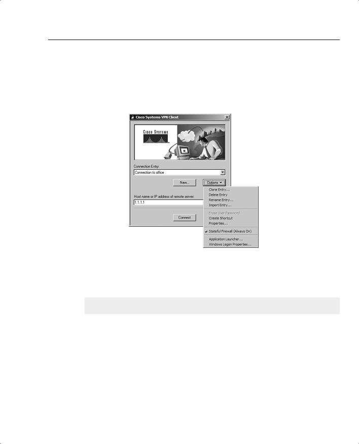
The Stateful Firewall feature is easily configured on the Cisco VPN Client. Open the client, as shown in Figure 6-4.
Figure 6-4 VPN Dialer
Configuring the VPN Concentrator for Firewall Usage 277
Choose the Options pull-down menu, as shown in Figure 6-5. If the Stateful Firewall (Always On) option does not have a check mark in front of it, click it once. Because the Options pulldown menu disappears, choose it again, and make sure that there is a check mark in front of the Stateful Firewall (Always On) option, as shown in Figure 6-5.
Figure 6-5 VPN Client Options Menu
Configuring the VPN Concentrator for Firewall Usage
24 Customizing firewall policy
Configuration of the firewall for the VPN Client is done on the Configuration | User Management | Groups | Modify screen under the Client FW tab (see Figure 6-6). This screen is used for configuring all firewall options other than the Stateful (Always On) option, which is configured on the VPN Client itself. The following sections describe each of the options that are shown in the Client FW tab.