We have variables to represent the vertex shader and its constant table. We have a teapot mesh variable, followed by a set of D3DXHANDLEs whose variable names describe the variable they refer to.
The Setup function performs the following tasks:
Creates the teapot mesh
Compiles the vertex shader
Creates the vertex shader based on the compiled code
Obtains handles to several variables in the shader program through the constant table
additional components that a flexibleFvertex format cannot describe. Therefore, we use a flexible vertex format instead of a vertex declara-
Initializes several of the shader variables through the constant
table |
Y |
|
|
L |
|
Note: For this application our vertex structure does not require any |
tion for this sample. Recall that a flexible vertex format description gets |
converted to a vertex declaration internally. |
|
|
|
M |
bool Setup() |
A |
{ |
|
|
|
|
|
HRESULT hr = 0; |
|
|
|
E |
|
|
T |
|
//
// Create geometry:
//
D3DXCreateTeapot(Device, &Teapot, 0);
//
// Compile shader
//
ID3DXBuffer* |
shader |
= |
0; |
ID3DXBuffer* |
errorBuffer = |
0; |
hr = D3DXCompileShaderFromFile( "diffuse.txt",
0,
0,
"Main", // entry point function name "vs_1_1",
D3DXSHADER_DEBUG, &shader, &errorBuffer, &DiffuseConstTable);
// output any error messages if( errorBuffer )
{
::MessageBox(0, (char*)errorBuffer->GetBufferPointer(), 0, 0); d3d::Release<ID3DXBuffer*>(errorBuffer);
Introduction to Vertex Shaders 305
}
if(FAILED(hr))
{
::MessageBox(0, "D3DXCompileShaderFromFile() - FAILED", 0, 0); return false;
}
//
// Create shader
//
hr = Device->CreateVertexShader( (DWORD*)shader->GetBufferPointer(), &DiffuseShader);
if(FAILED(hr))
{
::MessageBox(0, "CreateVertexShader - FAILED", 0, 0); return false;
}
d3d::Release<ID3DXBuffer*>(shader);
//
// Get Handles
//
ViewMatrixHandle = DiffuseConstTable->GetConstantByName(
0, "ViewMatrix");
ViewProjMatrixHandle = DiffuseConstTable->GetConstantByName(
0, "ViewProjMatrix");
AmbientMtrlHandle = DiffuseConstTable->GetConstantByName(
0, "AmbientMtrl");
DiffuseMtrlHandle = DiffuseConstTable->GetConstantByName(
0, "DiffuseMtrl");
LightDirHandle = DiffuseConstTable->GetConstantByName(
0, "LightDirection");
//
//Set shader constants:
//Light direction:
D3DXVECTOR4 directionToLight(-0.57f, 0.57f, -0.57f, 0.0f); DiffuseConstTable->SetVector(Device, LightDirHandle,
&directionToLight);
// Materials:
D3DXVECTOR4 ambientMtrl(0.0f, 0.0f, 1.0f, 1.0f); D3DXVECTOR4 diffuseMtrl(0.0f, 0.0f, 1.0f, 1.0f);
DiffuseConstTable->SetVector(Device,AmbientMtrlHandle,&ambientMtrl); DiffuseConstTable->SetVector(Device,DiffuseMtrlHandle,&diffuseMtrl); DiffuseConstTable->SetDefaults(Device);
306Chapter 17
//Compute projection matrix. D3DXMatrixPerspectiveFovLH(
&Proj, D3DX_PI * 0.25f,
(float)Width / (float)Height, 1.0f, 1000.0f);
return true;
}
The Display function is quite simple. It tests for user input and updates the view matrix accordingly. However, because we perform the view matrix transformation in the shader, we must also update the view matrix variable within the shader. We do this using the constant table:
bool Display(float timeDelta)
{
if( Device )
{
//
// Update view matrix code snipped...
//
D3DXMATRIX V;
D3DXMatrixLookAtLH(&V, &position, &target, &up);
DiffuseConstTable->SetMatrix(Device, ViewMatrixHandle, &V);
D3DXMATRIX ViewProj = V * Proj;
DiffuseConstTable->SetMatrix(Device, ViewProjMatrixHandle,
&ViewProj);
//
// Render
//
Device->Clear(0, 0, D3DCLEAR_TARGET | D3DCLEAR_ZBUFFER,
0xffffffff, 1.0f, 0);
Device->BeginScene();
Device->SetVertexShader(DiffuseShader);
Teapot->DrawSubset(0);
Device->EndScene(); Device->Present(0, 0, 0, 0);
}
return true;
}
Also observe that we enable the vertex shader that we wish to use right before the DrawSubset call.
Cleaning up is done as expected; we simply release the allocated interfaces:
void Cleanup()
{
d3d::Release<ID3DXMesh*>(Teapot);
Introduction to Vertex Shaders 307
d3d::Release<IDirect3DVertexShader9*>(DiffuseShader);
d3d::Release<ID3DXConstantTable*>(DiffuseConstTable);
}
17.5 Sample Application: Cartoon Rendering
As a second vertex shader sample, let’s write two vertex shaders that shade and outline a mesh in such a way that it appears as a cartoonstyle drawing. Figure 17.2 illustrates this:
Figure 17.2: (a) Objects shaded using cartoon shading (note the sharp transition between shades). (b) To enhance the cartoon effect, the silhouette edges are outlined. (c) Objects shaded using standard diffuse lighting.

Note: Cartoon rendering is a particular kind of non-photorealistic rendering, sometimes called stylistic rendering.
Although cartoon rendering isn’t for all games, such as violent firstperson shooters, it can enhance the atmosphere of some types of games when you want to impart a cartoonish feel. Furthermore, cartoon rendering is pretty easy to implement and allows us to demonstrate vertex shaders nicely.
We break cartoon rendering into two steps.
1.Cartoon drawings typically have few shading intensity levels with an abrupt transition from one shade to the next; we refer to this as cartoon shading. In Figure 17.2.a we see that the meshes are shaded using exactly three shading intensities (bright, medium, dark) and the transition between them is abrupt—unlike Figure 17.2.c, which has a smooth transition from light to dark.
2.Cartoon drawings also typically have their silhouette edges outlined, as Figure 17.2.b shows.
Both steps require their own vertex shader.
17.5.1 Cartoon Shading
To implement cartoon shading, we take the same approach as Lander describes in his article “Shades of Disney: Opaquing a 3D World” featured in the March 2000 issue of Game Developer Magazine. It works like this: We create a grayscale luminance texture that contains the different shade intensities we desire. Figure 17.3 shows the texture that we use in the sample program.
Figure 17.3: Shade texture holds the shade intensities we use. Observe the abrupt transitions between shades and that the texture shade intensity must increase from left to right.
Then in the vertex shader we perform the standard diffuse calculation dot product to determine the cosine of the angle between the vertex
normal N and the light vector L, which is used to determine how much light the vertex receives:
s L N
Introduction to Vertex Shaders 309
If s < 0, that implies the angle between the light vector and vertex nor-
mal is greater than 90 degrees, which implies that the surface receives no light. Therefore, if s < 0, we let s = 0. So s [0, 1].
Now, in the usual diffuse lighting model, we use s to scale our color vector such that the vertex colors are darkened based on the amount of light that they receive:
diffuseColor s(r, g, b, a)
However, this will result in a smooth transition from light to dark shades. This is the opposite of what we desire for cartoon shading. We want an abrupt transition between a few different shades (around two to four shades works well for cartoon rendering).
Instead of using s to scale the color vector, we are going to use it as the u texture coordinate for the luminance texture that we spoke of earlier—the one depicted in Figure 17.3.
Note: The scalar s is of course a valid texture coordinate since s [0, 1], which is the usual texture coordinate interval.
In this way the vertices won’t be shaded smoothly but rather abruptly. For example, the luminance texture might be divided into three shades, as Figure 17.4 shows.
Figure 17.4: The shade used depends on the interval the texture coordinate falls in.
Then values of s [0, 0.33] are shaded using shade 0, values of s (0.33, 0.66] are shaded using shade 1, and values of s (0.66, 1] are shaded
using shade 2. Of course, the transition from one of these shades to the next is abrupt, giving us the desired effect.
Note: We turn off texture filtering for cartoon shading as well because the filtering attempts to smooth out the shade transitions. This is undesirable since we want abrupt transitions.
17.5.2 The Cartoon Shading Vertex Shader Code
We now present the vertex shader for cartoon shading. The primary task of the shader is merely to compute and set the texture coordinate
based on s L N. Observe that in the output structure, we have added a data member to store the computed texture coordinate. Also note that we still output the color of the vertex, though we don’t modify it, and
when the color is combined with the luminance texture, it appears shaded.
//File: toon.txt
//Desc: Vertex shader that lights geometry so it appears to be
//drawn in a cartoon style.
//
// Globals
//
extern matrix WorldViewMatrix; extern matrix WorldViewProjMatrix;
extern vector Color;
extern vector LightDirection;
static vector Black = {0.0f, 0.0f, 0.0f, 0.0f};
//
// Structures
//
struct VS_INPUT
{
vector position : POSITION; vector normal : NORMAL;
};
struct VS_OUTPUT
{
vector position : POSITION; float2 uvCoords : TEXCOORD; vector diffuse : COLOR;
};
//
// Main
//
VS_OUTPUT Main(VS_INPUT input)
{
//zero out each member in output VS_OUTPUT output = (VS_OUTPUT)0;
//transform vertex position to homogenous clip space output.position = mul(input.position, WorldViewProjMatrix);
//
//Transform lights and normals to view space. Set w
//components to zero since we're transforming vectors.
//Assume there are no scalings in the world
//matrix as well.
//
LightDirection.w = 0.0f;
Introduction to Vertex Shaders 311
input.normal.w |
= 0.0f; |
LightDirection |
= mul(LightDirection, WorldViewMatrix); |
input.normal |
= mul(input.normal, WorldViewMatrix); |
//
// Compute the 1D texture coordinate for toon rendering.
//
float u = dot(LightDirection, input.normal);
//
//Clamp to zero if u is negative because u
//negative implies the angle between the light
//and normal is greater than 90 degrees. And
//if that is true then the surface receives
//no light.
//
if(u < 0.0f) u = 0.0f;
//
// Set other tex coord to middle.
//
float v = 0.5f;
output.uvCoords.x = u; output.uvCoords.y = v;
// save color output.diffuse = Color;
return output;
}
A couple of remarks:
We assume the world matrix doesn’t do any scaling because if it does, it can mess up the length and direction of a vector that multiplies it.
We always set the v texture coordinate to the middle of the texture. This implies that we are using only a single horizontal line in the texture, which implies we could use a 1D luminance texture instead of a 2D one. However, both 1D and 2D textures work. For the sample we have used a 2D texture over a 1D texture for no particular reason.
17.5.3 Silhouette Outlining
To complete the cartoon effect, we need to outline the silhouette edges. This is a bit more involved than cartoon shading.

17.5.3.1 Edge Representation
We represent an edge of a mesh as a quad (built from two triangles)— see Figure 17.5.
Figure 17.5: A quad to represent an edge
We choose quads for a couple of reasons: We can easily change the thickness of the edge by adjusting the dimensions of the quad, and we can render degenerate quads to hide certain edges, namely edges that are not silhouette edges. In Direct3D we build a quad out of two triangles. A degenerate quad is a quad built from two degenerate triangles. A degenerate triangle is a triangle with zero area or, in other words, a triangle defined by three vertices that lie on the same line (collinear). If we pass a degenerate triangle into the rendering pipeline, nothing is displayed for that triangle. This is useful because if we wish to hide a particular triangle we can simply degenerate it without actually removing it from our triangle list (vertex buffer). Recall that we only want to display the silhouette edges—not every edge of the mesh.
When we first create an edge, we specify its four vertices so that it is degenerate (Figure 17.6), which means the edge will be hidden (not displayed when rendered).
Figure 17.6: Degenerate quad describing the edge shared by the two triangles
Note that for the two vertices v0 and v1 in Figure 17.6, we set their vertex normal vector to the zero vector. Then when we feed the edge vertices into the vertex shader, the shader will test if a vertex is on a silhouette edge; if it is, then the vertex shader will offset the vertex position in the direction of the vertex normal by some scalar. Observe then that the vertices with a zero normal vector will not be offset.
Introduction to Vertex Shaders 313
Thus, we end up with a non-degenerate quad to represent the silhouette edge, as Figure 17.7 shows.
Figure 17.7: Vertices v2 and v3 on a silhouette edge being offset in the direction of their vertex normals n2 and n3 respectively. Observe that vertices v0 and v1 remain in their fixed position since their vertex normals equal the zero vector, thus no offset occurs for them. In this way the quad is successfully regenerated to represent the silhouette edge.
Remark: If we didn’t set the vertex normals of vertices v0 and v1 to the zero vector, then those vertices would have been offset as well. But if we offset all four of the vertices describing a silhouette edge, then we have only translated the degenerate quad. By keeping vertices v0 and v1 fixed and only offsetting vertices v2 and v3 we regenerate the quad.
17.5.3.2 Testing for a Silhouette Edge
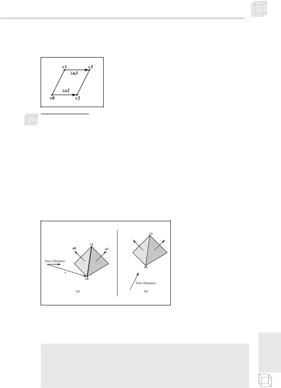
An edge is a silhouette edge if the two faces, face0 and face1, sharing that edge face in different directions relative to the viewing direction. That is, if one face is front facing and the other face is back facing, then the edge is a silhouette edge. Figure 17.8 gives an example of a silhouette edge and a non-silhouette edge.
Figure 17.8: In (a), one face that shares the edge defined by the vertices v0 and v1 is front facing and the other face that shares the edge is back facing, thus the edge is a silhouette edge. In (b), the faces that share the edge defined by v0 and v1 are both front facing, and therefore the edge is not a silhouette edge.
It follows then that in order to test if a vertex is on a silhouette edge, we must know the normal vectors of face0 and face1 on a per vertex basis. Our edge vertex data structure reflects this:
struct VS_INPUT |
|
{ |
|
vector position |
: POSITION; |
vector normal |
: NORMAL0; |
vector faceNormal1 |
: NORMAL1; |
vector faceNormal2 : NORMAL2;
};