

Fundamentals of Microelectronics
.pdfBR |
Wiley/Razavi/Fundamentals of Microelectronics [Razavi.cls v. 2006] |
June 30, 2007 at 13:42 |
231 (1) |
|
|
|
|
Sec. 5.3 Bipolar Amplifier Topologies |
|
|
|
231 |
VCC |
|
|
|
VCC |
R C |
|
R C |
|
R1 |
Vout |
|
Vout |
I 1 |
|
Q 1 |
Vb |
Q 1 |
|
|
I B |
|
|||
|
|
|
R2 |
|
|
|
|
|
|
Vin 600 mV |
|
Vin 600 mV |
|
|
Thermometer
(b)
(a)
Figure 5.63 (a) CB stage sensing an input, (b) bias network for base.
The reader is encouraged to repeat the problem with IC = 0:4 mA to verify that the maximum gain remains relatively independent of the bias current.10
We must now generate Vb. A simple approach is to employ a resistive divider as depicted in Fig. 5.63(b). To lower sensitivity to , we choose I1 10IB 20 A VCC=(R1 + R2). Thus, R1 + R2 = 90 k . Also,
Vb |
R2 |
VCC |
(5.260) |
R1 + R2 |
|||
and hence |
|
|
|
R2 |
= 67:7 k |
(5.261) |
|
R1 |
= 22:3 k : |
(5.262) |
|
Exercise
Repeat the above example if the thermometer voltage is 300 mV.
Let us now compute the I/O impedances of the CB topology so as to understand its capabilities in interfacing with preceding and following stages. The rules illustrated in Fig. 5.7 prove extremely useful here, obviating the need for small-signal equivalent circuits. Shown in Fig. 5.64(a), the simplified ac circuit reveals that Rin is simply the impedance seen looking into the emitter with the base at ac ground. From the rules in Fig. 5.7, we have
R = |
1 |
(5.263) |
in gm
if VA = 1. The input impedance of the CB stage is therefore relatively low, e.g., 26 for IC = 1 mA (in sharp contrast to the corresponding value for a CE stage, =gm).
10This example serves only as an illustration of the CB stage. A CE stage may prove more suited to sensing a thermometer voltage.

BR |
Wiley/Razavi/Fundamentals of Microelectronics [Razavi.cls v. 2006] |
June 30, 2007 at 13:42 |
232 (1) |
|
|
|
|
232 |
Chap. 5 |
Bipolar Amplifiers |
VCC |
VCC |
|
R C |
R C |
|
Q 1 |
Q 1 |
Vb |
ac |
I X |
|
|
|
|
VX |
V |
|
R in |
|
|
(a) |
(b) |
|
Figure 5.64 (a) Input impedance of CB stage, (b) response to a small change in input.
The input impedance of the CB stage can also be determined intuitively [Fig. 5.64(b)]. Suppose a voltage source VX tied to the emitter of Q1 changes by a small amount V . The baseemitter voltage therefore changes by the same amount, leading to a change in the collector current equal to gm V . Since the collector current flows through the input source, the current supplied by VX also changes by gm V . Consequently, Rin = VX = IX = 1=gm.
Does an amplifier with a low input impedance find any practical use? Yes, indeed. For example, many stand-alone high-frequency amplifiers are designed with an input resistance of 50 to provide “impedance matching” between modules in a cascade and the transmission lines (traces on a printed-circuit board) connecting the modules (Fig. 5.65).11
50− Ω |
50− Ω |
Transmission |
Transmission |
Line |
Line |
50 Ω |
50 Ω |
Figure 5.65 System using transmission lines.
The output impedance of the CB stage is computed with the aid of Fig. 5.66, where the input voltage source is set to zero. We note that Rout = Rout1jjRC, where Rout1 is the impedance seen at the collector with the emitter grounded. From the rules of Fig. 5.7, we have Rout1 = rO and hence
Q 1 |
|
RC |
r O |
R out1 |
R out |
ac
Figure 5.66 Output impedance of CB stage.
Rout = rOjjRC |
(5.264) |
11If the input impedance of each stage is not matched to the characteristic impedance of the preceding transmission line, then “reflections” occur, corrupting the signal or at least creating dependence on the length of the lines.

BR |
Wiley/Razavi/Fundamentals of Microelectronics [Razavi.cls v. 2006] |
June 30, 2007 at 13:42 |
233 (1) |
|
|
|
|
Sec. 5.3 Bipolar Amplifier Topologies |
233 |
or |
|
Rout = RC if VA = 1: |
(5.265) |
Example 5.36
A common-base amplifier is designed for an input impedance of Rin and an output impedance of Rout. Neglecting the Early effect, determine the voltage gain of the circuit.
Solution
Since Rin = 1=gm and Rout = RC, we have |
|
|
Av = |
Rout : |
(5.266) |
|
Rin |
|
Exercise
Compare this value with that obtained for the CE stage.
From Eqs. (5.256) and (5.266), we conclude that the CB stage exhibits a set of trade-offs similar to those depicted in Fig. 5.33 for the CE amplifier.
It is instructive to study the behavior of the CB topology in the presence of a finite source resistance. Shown in Fig. 5.67, such a circuit suffers from signal attenuation from the input to node X, thereby providing a smaller voltage gain. More specifically, since the impedance seen looking into the emitter of Q1 (with the base grounded) is equal to 1=gm (for VA = 1), we have
VCC
|
|
|
|
|
|
|
R C |
|
|
|
|
|
|
v out |
|
|
|
|
|
|
|
|
|
|
|
|
|
||||||||
|
|
|
|
|
|
|
|
|
|
|
|
|
|
|
|
|
|
|
|
|
|
|
|
|
|||||||||||
|
|
|
|
|
|
|
|
|
|
|
|
|
|
|
|
|
|
|
|
|
|
|
|
|
|
|
|
|
|
|
|||||
|
|
|
|
|
|
|
|
|
|
|
|
|
|
|
|
|
|
|
|
|
|
|
|
|
|
|
|
|
|
||||||
|
|
|
|
RS |
|
Q 1 |
|
|
|
|
|
|
|
|
|
|
|
|
|
|
|
|
|
|
|
|
|
|
|||||||
|
|
|
|
|
|
|
|
|
|
|
|
|
|
|
|
|
|
|
|
|
|
|
|
|
|
|
|||||||||
|
|
|
|
|
|
|
|
|
|
|
|
|
|
|
|
|
|
|
|
|
|
|
|
|
|
|
|||||||||
|
|
|
|
|
|
|
|
|
|
|
X |
|
|
|
|
|
|
|
|
|
|
RS |
|
||||||||||||
|
|
|
|
|
|
|
|
|
|
|
|
|
|
|
|
|
|
|
|
|
|
|
|
|
|||||||||||
|
|
|
|
|
|
|
|
|
|
|
|
|
|
|
|
|
|
|
|
|
|
|
|
|
|||||||||||
|
|
|
|
|
|
|
|
|
|
|
|
|
|
|
|
|
|
|
|
|
|
|
|
|
|
|
|||||||||
v in |
|
|
|
|
|
|
|
|
|
|
|
|
|
|
|
|
|
|
|
|
|
|
|
|
|
|
|
|
|
|
X |
|
|||
|
|
|
|
|
|
|
|
|
|
|
|
|
|
|
|
|
|
|
|
|
|
|
|
|
|
|
|
|
|
|
|||||
|
|
|
|
|
|
1 |
|
|
|
|
|
|
|
|
|
|
|
|
|
v in |
|
|
|
|
|
|
|
|
1 |
|
|
||||
|
|
|
|
|
|
|
|
|
|
|
|
|
|
|
|
|
|
|
|
|
|
|
|||||||||||||
|
|
|
|
|
|
g m |
|
|
|
|
|
|
|
|
|
|
|
|
|
|
|
|
|
|
g m |
|
|||||||||
|
|
|
|
|
|
|
|
|
|
|
|
|
|
|
|
|
|
|
|
||||||||||||||||
|
|
|
|
|
|
|
|
|
|
|
|
|
|
|
|
|
|
|
|
|
|
|
|
|
|
||||||||||
Figure 5.67 CB stage with source resistance. |
|
|
|
|
|
|
|
|
|
|
|
|
|
|
|
|
|
|
|
|
|
|
|
|
|
|
|
|
|
||||||
|
|
|
|
|
|
|
|
|
|
|
|
|
|
|
|
|
|
|
|
|
|
|
|
|
|
|
|
|
|||||||
|
|
|
|
|
|
|
1 |
|
|
|
|
|
|
|
|
|
|
|
|
|
|
|
|
|
|
|
|
|
|
||||||
|
|
|
|
|
|
|
|
|
|
|
|
|
|
|
|
|
|
|
|
|
|
|
|
|
|
|
|
|
|
|
|
||||
|
|
vX = |
|
|
|
gm |
|
|
|
vin |
|
|
|
|
|
|
|
|
|
|
|
|
(5.267) |
||||||||||||
|
|
RS + |
|
1 |
|
|
|
|
|
|
|
|
|
|
|
|
|
||||||||||||||||||
|
|
|
|
|
|
|
gm |
|
|
|
|
|
|
|
|
|
|
|
|
|
|
|
|||||||||||||
|
= |
|
|
1 |
|
|
|
|
|
vin: |
|
|
|
|
|
|
|
|
|
|
|
|
(5.268) |
||||||||||||
|
|
|
|
|
|
|
|
|
|
|
|
|
|
|
|
|
|
|
|
|
|
|
|
|
|
|
|
||||||||
|
|
|
|
|
|
|
|
|
|
|
|
|
|
|
|
|
|
|
|
|
|
|
|
|
|
|
|
||||||||
|
|
|
|
|
|
|
1 + gmRS |
|
|
|
|
|
|
|
|
|
|
|
|
|
|||||||||||||||
We also recall from Eq. (5.254) that the gain from the emitter to the output is given by |
|
||||||||||||||||||||||||||||||||||
|
|
|
|
vout = g |
m |
R : |
|
|
|
|
|
|
|
|
|
|
|
|
(5.269) |
||||||||||||||||
|
|
|
|
vX |
|
|
|
|
|
|
|
|
C |
|
|
|
|
|
|
|
|
|
|
|
|
|
|||||||||
|
|
|
|
|
|
|
|
|
|
|
|
|
|
|
|
|
|
|
|
|
|
|
|
|
|
|
|
|
|
|
|
|
|||

BR |
Wiley/Razavi/Fundamentals of Microelectronics [Razavi.cls v. 2006] |
June 30, 2007 at 13:42 |
234 (1) |
|
|
|
|
234 Chap. 5 Bipolar Amplifiers
It follows that |
|
|
|
|
|
|
vout = |
|
gmRC |
|
|
(5.270) |
|
|
|
|
|
|
||
vin |
1 + gmRS |
|
||||
= |
|
|
RC |
; |
(5.271) |
|
1 |
+ RS |
|||||
|
|
|
|
|
|
|
|
|
gm |
|
|
|
|
a result identical to that of the CE stage (except for a negative sign) if RS is viewed as an emitter degeneration resistor.
Example 5.37
A common-base stage is designed to amplify an RF signal received by a 50antenna. Determine the required bias current if the input impedance of the amplifier must “match” the impedance of the antenna. What is the voltage gain if the CB stage also drives a 50load? Assume VA = 1.
Solution
Figure 5.68 depicts the amplifier 12 and the equivalent circuit with the antenna modeled by a
|
|
VCC |
|
VCC |
|
|
R C |
|
R C |
|
|
|
|
v out |
Antenna |
v out |
|
Antenna |
Q 1 |
VB |
VB |
||
Q 1 |
|||||
|
|
|
RS |
|
|
|
|
|
v in |
|
Figure 5.68 (a) CB stage sensing a signal received by an antenna, (b) equivalent circuit.
voltage source, vin, and a resistance, RS = 50 . For impedance matching, it is necessary that the input impedance of the CB core, 1=gm, be equal to RS, and hence
IC = gmVT
= 0:52 mA:
If RC itself is replaced by a 50load, then Eq. (5.271) reveals that
Av = 1 RC gm + RS
= 12:
The circuit is therefore not suited to driving a 50load directly.
(5.272)
(5.273)
(5.274)
(5.275)
12The dots denote the need for biasing circuitry, as described later in this section.

BR |
Wiley/Razavi/Fundamentals of Microelectronics [Razavi.cls v. 2006] |
June 30, 2007 at 13:42 |
235 (1) |
|
|
|
|
Sec. 5.3 |
Bipolar Amplifier Topologies |
235 |
Exercise
What is the voltage gain if a 50resistor is also tied from the emitter of Q1 to ground?
Another interesting point of contrast between the CE and CB stages relates to their current gains. The CB stage displays a current gain of unity because the current flowing into the emitter simply emerges from the collector (if the base current is neglected). On the other hand, as mentioned in Section 5.3.1, AI = for the CE stage. In fact, in the above example,
iin = vin=(RS + 1=gm), which upon flowing through RC, yields vout = RC vin=(RS + 1=gm). It is thus not surprising that the voltage gain does not exceed 0.5 if RC RS.
As with the CE stage, we may desire to analyze the CB topology in the general case: with emitter degeneration, VA < 1, and a resistance in series with the base [Fig. 5.69(a)]. Outlined in Problem 64, this analysis is somewhat beyond the scope of this book. Nevertheless, it is in-
VCC
|
R C |
|
|
|
|
|
|
|
|
|
v out |
|
r O |
|
|
|
|
|
r O |
|
VB |
RE |
|
R |
C |
|
|
|
|
|
|
||||
RE |
Q 1 |
R |
B |
|
Q 1 |
R out1 |
|
R out2 |
|
|
|
|
|
|
|
||
v in |
|
|
|
|
|
|
|
|
|
(a) |
|
|
|
|
(b) |
|
|
Figure 5.69 (a) General CB stage, (b) output impedance seen at different nodes.
structive to consider a special case where RB = 0 but VA < 1, and we wish to compute the output impedance. As illustrated in Fig. 5.69(b), Rout is equal to RC in parallel with the impedance seen looking into the collector, Rout1. But Rout1 is identical to the output resistance of an emitter-degenerated common emitter stage, i.e., Fig. 5.46, and hence given by Eq. (5.197):
Rout1 = [1 + gm(REjjr )]rO + (REjjr ): |
(5.276) |
It follows that |
|
Rout = RCjj f[1 + gm(REjjr )]rO + (REjjr )g : |
(5.277) |
The reader may have recognized that the output impedance of the CB stage is equal to that of the CE stage. Is this true in general? Recall that the output impedance is determined by setting the input source to zero. In other words, when calculating Rout, we have no knowledge of the input terminal of the circuit, as illustrated in Fig. 5.70 for CE and CB stages. It is therefore no coincidence that the output impedances are identical if the same assumptions are made for both circuits (e.g., identical values of VA and emitter degeneration).
Example 5.38
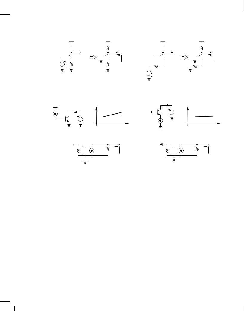
Old wisdom says “the output impedance of the CB stage is substantially higher than that of the CE stage.” This claim is justified by the tests illustrated in Fig. 5.71. If a constant current is
injected into the base while the collector voltage is varied, IC exhibits a slope equal to r,1 [Fig.
O
5.71(a)]. On the other hand, if a constant current is drawn from the emitter, IC displays much less dependence on the collector voltage. Explain why these tests do not represent practical situations.
BR |
Wiley/Razavi/Fundamentals of Microelectronics [Razavi.cls v. 2006] |
June 30, 2007 at 13:42 |
236 (1) |
|
|
|
|
236 |
Chap. 5 |
Bipolar Amplifiers |
VCC
 RC
RC
v out


 Q 1
Q 1
v in |
RE |
(a)
VCC
RC |


 Q 1
Q 1
RE R out
VCC
 RC
RC
v out
Vb 

 Q 1
Q 1
R E
v in
(b)
Figure 5.70 (a) CE stage and (b) CB stage simplified for output impedance calculation.
I C
VCC
RC |


 Q 1
Q 1
R out
R E
VCC |
I C |
|
I C |
VB |
Q 1 |
V1 |
I C |
I B |
|
|
|
|
|||
|
Q 1 |
V1 |
|
|
I E |
|
|
|
|
|
|
|
|
|
|
|
|
|
V1 |
|
|
|
V1 |
|
|
(a) |
|
|
|
|
(b) |
Open |
|
|
|
|
|
|
|
|
r π |
vπ |
gm vπ r O |
|
r π |
vπ |
gm vπ r O |
|
|
|
R out |
|
|
|
R out |
|
|
|
|
|
|
Open |
|
|
|
(c) |
|
|
|
|
(d) |
Figure 5.71 (a) Resistance seens at collector with emitter grounded, (b) resistance seen at collector with an ideal current source in emitter, (c) small-signal model of (a), (d) small-signal model of (b).
Solution
The principal issue in these tests relates to the use of current sources to drive each stage. From a small-signal point of view, the two circuits reduce to those depicted in Figs. 5.71(c) and (d), with current sources IB and IE replaced with open circuits because they are constant. In Fig. 5.71(c), the current through r is zero, yielding gmv = 0 and hence Rout = rO. On the other hand, Fig. 5.71(d) resembles an emitter-degenerated stage (Fig. 5.46) with an infinite emitter resistance, exhibiting an output resistance of
Rout = [1 + gm(REjjr )]rO + (REjjr ) |
(5.278) |
= (1 + gmr )rO + r |
(5.279) |
rO + r ; |
(5.280) |
which is, of course, much greater than rO. In practice, however, each stage may be driven by a voltage source having a finite impedance, making the above comparison irrelevant.
Exercise
Repeat the above example if a resistor of value R1 is inserted in series with the emitter.

BR |
Wiley/Razavi/Fundamentals of Microelectronics [Razavi.cls v. 2006] |
June 30, 2007 at 13:42 |
237 (1) |
|
|
|
|
Sec. 5.3 |
Bipolar Amplifier Topologies |
237 |
Another special case of the topology shown in Fig. 5.69(a) occurs if VA = 1 but RB > 0. Since this case does not reduce to any of the configurations studied earlier, we employ the smallsignal model shown in Fig. 5.72 to study its behavior. As usual, we write gmv = ,vout=RC and hence v = ,vout=(gmRC). The current flowing through r (and RB) is then equal to
v =r = ,vout=(gmr RC ) = ,vout=( RC). Multiplying this current by RB + r , we obtain the voltage at node P :
RB
 v out
v out
r π vπ |
gm vπ RC |
|
P |
R E
v in
Figure 5.72 CB stage with base resistance.
|
|
|
|
vP |
= ,,vout (RB + r ) |
|
|
|
|||||||||||||||
|
|
|
|
|
|
|
|
|
|
RC |
|
|
|
|
|
||||||||
|
|
|
|
|
= |
|
vout |
(RB + r ): |
|
|
|
|
|
||||||||||
|
|
|
|
|
|
|
|
|
|
|
|
||||||||||||
|
|
|
|
|
|
|
|
RC |
|
|
|
|
|
|
|
|
|
|
|
|
|||
We also write a KCL at P : |
|
|
|
|
|
|
|
|
|
|
|
|
|
|
|
|
|
|
|
|
|
|
|
|
|
|
|
v + gmv |
= vP , vin ; |
|
|
|
|||||||||||||||
|
|
|
|
r |
|
|
|
|
|
|
|
|
|
|
|
RE |
|
|
|
|
|
||
that is, |
|
|
|
|
|
|
|
|
|
|
|
|
|
|
|
|
|
|
|
|
|
|
|
|
|
|
|
|
|
|
|
|
|
|
|
|
|
|
vout |
|
|
|
|
|
|||
|
1 |
|
|
|
|
vout |
|
|
|
|
|
|
(RB |
+ r ) , vin |
|||||||||
|
|
|
|
|
|
|
|
|
RC |
||||||||||||||
|
|
+ g |
m |
, |
|
|
|
|
= |
|
|
|
|
|
|
|
|
|
|
|
: |
||
|
r |
|
gmRC |
|
|
|
|
|
|
|
RE |
|
|
|
|||||||||
It follows that |
|
|
|
|
|
|
|
|
|
|
|
|
|
|
|
|
|
|
|
|
|
|
|
|
|
vout = |
|
|
|
|
|
|
|
|
|
RC |
|
|
|
: |
|
||||||
|
|
|
|
|
|
|
|
|
|
|
|
|
|
|
|
|
|
|
|||||
|
|
vin |
|
|
( + 1)RE + RB + r |
||||||||||||||||||
Dividing the numerator and denominator by + 1, we have |
|
|
|
||||||||||||||||||||
|
|
|
vout |
|
|
|
|
|
|
|
|
RC |
|
|
: |
|
|
||||||
|
|
|
vin |
|
|
|
|
|
|
|
RB |
1 |
|
|
|
||||||||
|
|
|
|
|
|
|
|
|
|
|
|
|
|
|
|
|
|||||||
|
|
|
|
|
|
|
|
|
RE + |
+ 1 |
+ |
gm |
|
|
|
|
|||||||
(5.281)
(5.282)
(5.283)
(5.284)
(5.285)
(5.286)
As expected, the gain is positive. Furthermore, this expression is identical to that in (5.185) for the CE stage. Figure 5.73 illustrates the results, revealing that, except for a negative sign, the two stages exhibit equal gains. Note that RB degrades the gain and is not added to the circuit deliberately. As explained later in this section, RB may arise from the biasing network.
Let us now determine the input impedance of the CB stage in the presence of a resistance in series with the base, still assuming VA = 1. From the small-signal equivalent circuit shown in

BR |
Wiley/Razavi/Fundamentals of Microelectronics [Razavi.cls v. 2006] |
June 30, 2007 at 13:42 |
238 (1) |
|
|
|
|
238 |
Chap. 5 |
Bipolar Amplifiers |
|
VCC |
|
VCC |
|
RC |
|
RC |
RB |
v out |
RB |
v out |
|
Q 1 |
|
Q 1 |
v in |
RE |
|
RE |
|
|
v in
Figure 5.73 Comparison of CE and CB stages with base resistance.
Fig. 5.74, we recognize that r and RB form a voltage divider, thereby producing13
RB
|
|
|
|
|
|
|
|
|
|
|
|
|
|
|
|
|
|
|
|
|
|
|
|
|
|
|
|
|
|
|
|
v out |
|
|
|
|
|
|
|
|
|
|
r π |
|
vπ |
|
gm vπ |
|
RC |
||||||||||||||||
|
|
|
|
|
|
|
|
|
|
|
||||||||||||||||||||||
|
|
|
|
|
|
|
|
|
|
|
|
|
|
|
|
|
|
|
|
|
|
|
|
|
|
|
|
|
|
|
|
|
|
|
|
|
|
|
|
|
|
|
|
|
|
|
|
|
|
|
|
|
|
|
|
|
|
|
|
|
|
|
|
|
|
|
|
v X |
|
|
|
|
|
|
|
i X |
|
|
|
|
|
|
|
|
|
|
|
|
|
|
|
|
||||||
|
|
|
|
|
|
|
|
|
|
|
|
|
|
|
|
|
|
|
|
|
|
|
|
|
|
|
||||||
|
|
|
|
|
|
|
|
|
|
|
|
|
|
|
|
|
|
|
||||||||||||||
|
|
|
|
|
|
|
|
|
|
|
|
|
|
|
|
|
||||||||||||||||
Figure 5.74 Input impedance of CB stage with base resistance. |
|
|||||||||||||||||||||||||||||||
|
|
|
|
|
|
|
|
v = , |
|
|
|
|
r |
|
|
vX : |
|
|||||||||||||||
|
|
|
|
|
|
|
|
|
|
|
|
|
|
|
|
|||||||||||||||||
|
|
|
|
|
|
|
|
|
|
|
|
|
|
|
|
|
|
r + RB |
|
|
|
|
|
|
|
|||||||
Moreover, KCL at the input node gives |
|
|
|
|
|
|
|
|
|
|
|
|
|
|
|
|
|
|
|
|
||||||||||||
|
|
|
|
|
|
|
|
|
v + g |
|
|
|
|
v = ,i |
X |
: |
|
|
|
|
|
|||||||||||
|
|
|
|
|
|
|
|
|
r |
|
|
m |
|
|
|
|
|
|
|
|
|
|||||||||||
|
|
|
|
|
|
|
|
|
|
|
|
|
|
|
|
|
|
|
|
|
|
|
|
|
|
|
||||||
Thus, |
|
|
|
|
|
|
|
|
|
|
|
|
|
|
|
|
|
|
|
|
|
|
|
|
|
|
|
|
|
|
|
|
|
|
1 |
+ g |
|
|
|
|
,r |
|
v = ,i |
|
|||||||||||||||||||||
|
|
|
|
|
|
|||||||||||||||||||||||||||
|
r |
|
|
|
|
|
m |
|
r + RB X |
|
|
|
|
|
X |
|||||||||||||||||
and |
|
|
|
|
|
|
|
|
|
|
|
|
|
|
|
|
|
|
|
|
|
|
|
|
|
|
|
|
|
|
|
|
|
|
|
|
|
|
|
|
vX = r + RB |
|
|
|
|
|
|
|
|||||||||||||||||
|
|
|
|
|
|
|
|
|
iX |
|
|
|
|
|
+ 1 |
|
|
|
|
|
|
|
||||||||||
|
|
|
|
|
|
|
|
|
|
|
|
|
|
|
|
|
1 |
+ |
RB |
: |
|
|
|
|
|
|||||||
|
|
|
|
|
|
|
|
|
|
|
|
|
|
|
|
|
|
|
|
|
|
|
|
|
|
|||||||
|
|
|
|
|
|
|
|
|
|
|
|
|
|
|
|
|
gm |
+ 1 |
|
|
|
|
|
|
||||||||
(5.287)
(5.288)
(5.289)
(5.290)
(5.291)
Note that Rin = 1=gm if RB = 0, an expected result from the rules illustrated in Fig. 5.7. Interestingly, the base resistance is divided by + 1 when “seen” from the emitter. This is in contrast to the case of emitter degeneration, where the emitter resistance is multiplied by + 1
13Alternatively, the current through r +RB is equal to vX=(r +RB), yielding a voltage of ,r vX =(r +RB) across r .

BR |
Wiley/Razavi/Fundamentals of Microelectronics [Razavi.cls v. 2006] |
June 30, 2007 at 13:42 |
239 (1) |
|
|
|
|
Sec. 5.3 |
Bipolar Amplifier Topologies |
239 |
when seen from the base. Figure 5.75 summarizes the two cases. Interestingly, these results remain independent of RC if VA = 1.
|
|
RB |
VA = |
|
|
|
VA = |
|
|
|
Q 1 |
|
|
|
Q 1 |
1 |
+ |
RB |
|
r |
π |
+ (β+1) R |
RE |
g m |
β+1 |
|
|
|
E |
Figure 5.75 Impedance seen at the emitter or base of a transistor.
Example 5.39
Determine the impedance seen at the emitter of Q2 identical and VA = 1.
|
VCC |
RB |
RC |
Q 1 |
v out |
|
Q 2 |
R eq |
R X |
in Fig. 5.76(a) if the two transistors are
|
|
VCC |
1 |
RB |
RC |
g m1+ |
β+1 |
v out |

 Q 2
Q 2
 R X
R X
(a) |
(b) |
Figure 5.76 (a) Example of CB stage, (b) simplified circuit.
Solution
The circuit employs Q2 as a common-base device, but with its base tied to a finite series resistance equal to that seen at the emitter of Q1. Thus, we must first obtain the equivalent resistance Req, which from Eq. (5.291) is simply equal to
Req = |
1 |
+ |
RB |
: |
(5.292) |
|
gm1 |
+ 1 |
|||||
|
|
|
|
Reducing the circuit to that shown in Fig. 5.76(b), we have
RX = |
1 |
+ |
Req |
|
|
|
|
|
|
(5.293) |
|
gm2 |
+ 1 |
|
|
|
|
|
|
||||
|
|
|
|
|
|
|
|
|
|||
= |
1 |
+ |
1 |
|
1 |
+ |
RB |
|
: |
(5.294) |
|
gm2 |
+ 1 |
gm1 |
+ 1 |
||||||||
|
|
|
|
|
|
||||||
Exercise
What happens if a resistor of value R1 is placed in series with the collector of Q1?
CB Stage with Biasing Having learned the small-signal properties of the CB core, we now extend our analysis to the circuit including biasing. An example proves instructive at this point.

BR |
Wiley/Razavi/Fundamentals of Microelectronics [Razavi.cls v. 2006] |
June 30, 2007 at 13:42 |
240 (1) |
|
|
|
|
240 |
Chap. 5 |
Bipolar Amplifiers |
Example 5.40
The student in Example 5.31 decides to incorporate ac coupling at the input of a CB stage to ensure the bias is not affected by the signal source, drawing the design as shown in Fig. 5.77. Explain why this circuit does not work.
VCC
R C
 Vout
Vout
Q 1 


Vb
Vin C1
Figure 5.77 CB stage lacking bias current.
Solution
Unfortunately, the design provides no dc path for the emitter current of Q1, forcing a zero bias current and hence a zero transconductance. The situation is similar to the CE counterpart in Example 5.5, where no base current can be supported.
Exercise
In what region does Q1 operate if Vb = VCC?
Example 5.41
Somewhat embarrassed, the student quickly connects the emitter to ground so that VBE = Vb and a reasonable collector current can be established (Fig. 5.78). Explain why “haste makes waste.”
VCC
R C
 v out
v out
Q 1 

Vb
v in C1
Figure 5.78 CB stage with emitter shorted to ground.
Solution
As with Example 5.6, the student has shorted the signal to ac ground. That is, the emitter voltage is equal to zero regardless of the value of vin, yielding vout = 0.