

1 Machine specification
Item |
Unit |
TY-290TE-6S-BS |
Mould-holders |
||
Number of stations |
No. |
6 |
Clamping force |
Kn |
170 |
Mould-holder dimensions |
in m |
290*550*2 |
Mould height |
mm |
100-250 |
Opening stroke of the mould-holder |
mm |
350 |
Heating plate (Independent temp, control) |
No. |
4*4 |
Heating type |
|
Heater |
Heating power (each station) |
Kw |
12.8 |
Injection groups |
||
Injection unit |
No. |
2 |
Screw diameter |
mm |
D65 |
Max. injection volume |
cm3 |
1290 |
Screw speed |
RPM |
0-150 (Adjustable) |
Thermal zone of barrel |
No. |
4 |
Injection pressure |
Bar/cm2 |
130 |
Power consumption |
||
Injection unit heating |
Kw |
13.4 |
Heating plate |
Kw |
76.8 |
Motor for hydraulic |
Kw |
37.5 |
Total Electric Consumption |
Kw |
127.7 |
Machine dimension (LxWxH) |
m |
8.1*4.2*3 |
Weight (Approximate) |
Tons |
32 |
*The
above value is only for reference
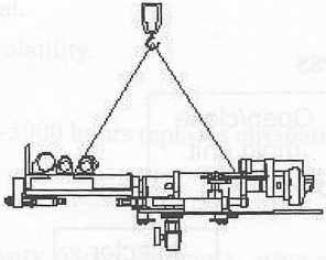
Installation and transportation
The machine decompose into several portion, some portion install in container. Using forklift truck or crane to unload the portion.
![]()


8
1450KG
5G0KG
0 4 2-KG

2
rn.
CD
.3 20 KG
900KG
<2&)
4 9 0.0 KG (2&)
I
I
a
a
a
a
a
a
a
a
is
Keep the foundation surface smooth
Ground
Crushed stone thickness above 200m/m
QOODOOOO0OOD
Concrete thickness above 150m/m
3-2 Installation process
3-1 Installation
Refer to the drawing B for installation the machine, so as to keep the machine the best efficiency and productivity.
Rigid and even foundation can prevent the machine from vibration, therefore, to keep the machine accuracy, performance for a long run, the sub-soil should be impacted to keep the foundation hard enough to ensure the machine weight and machine vibration. The machine encloses foundation bolts for foundation the machine.
Foundation notices:
Foundation can prevent the machine from vibration.
Foundation surface must be leveled.
The foundation strength should be above 150Kg/cnr.
Using the level gauge to adjust the leveling.
■
i
i
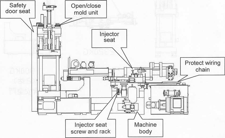
Place the machine body at most stable foundation.
Calibrate the machine level.
Assemble the injector.
Install the injector gear and rack.
Assemble the open/close mold unit and injector seat.
Assemble safety door unit.
Assemble the protect wiring chain.
According to the number connect the safety net by sequence.
According to the number tighten the oil pipe by sequence.
Assemble the air compressor, autoloader and cooler pipe.
Grounded the machine wire.
3-3 Recommended circulating lubricant and filling
The machine is driven by hydraulic mechanism, so it is very important to select the hydraulic oil. The condition of selecting oil must be following characteristic:
It must be effective to transmit the kinetic energy.
It must be enough mechanism lubricity. Improper lubrication oil will result into parts wear, pressure unstableness and decrease machine life times.
Suitable viscosity.
Stability for long time use.
Suitable for various oil seal.
Fine fire-resistance, less volatility.
Endurance compression.
* Every operating time 4500-5000 hours replaces circulating oil and cleans the oil tank.
3-1 Hydraulic oil
At 40°C, using viscosity 68cst, antiknock, wear resistance and antifriction lubrication oil. The recommended lubrication oil is as follows:
Brand |
Specification |
Density |
Flash point |
Flow point |
Viscosity (cst) |
Index of |
|
kg/1 |
°C |
°C |
40 °C |
100°C |
viscosity |
||
SHELL |
TELLUS 68 |
0.876 |
242 |
-30 |
68 |
9.3 |
114 |
SUPER GRADE |
GRADE AW68 |
0.88 |
222 |
-25 |
67 |
8.84 |
100 |
ELF |
PLOYTELIS |
0.887 |
240 |
-24 |
69.4 |
69.4 |
97 |
1 PI iwi
3
T:
-2 Lubrication oil of Injection unit
At 40°C, using viscosity 90cst, antiknock, wear resistance and antifriction I urn;:: The recommended lubrication oil is as follows:
Brand |
Specification |
Flash point |
Flow point |
Viscosity |
SUPER GRADE |
GRADE90 |
254 |
-15 |
96 |

Brand |
Specification |
Flow point °C |
Viscosity (25 °C) |
SHELL |
ALVINIA EP 2 |
180 |
265-295 |
SUPER GRADE |
NLGIGRADE 2 |
196 |
270-285 |
Refer
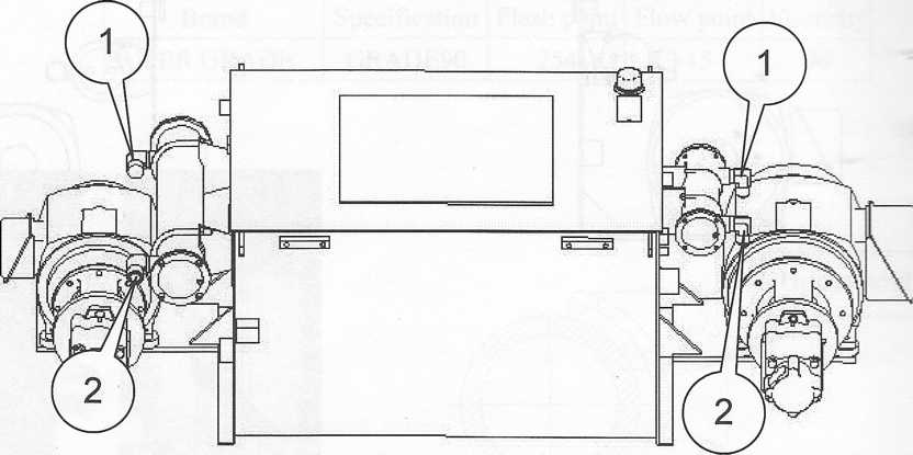
to the chapter 6 for lubrication points.
3-4 The recommended of pneumatic system oil
Brand |
Specification |
Density |
Flash point |
Flow point |
Viscosity |
SHELL |
TONNA32 |
0.935 |
242 |
-40 |
32 |
The
pneumatic system which uses release agent cannot fill with
lubrication oil.
3-5 The recommended of vacuum pump oil
Brand |
ESSO |
MOBIL |
TEXACO |
Model |
Esso Motor-0il30 |
Mobil oil 30 |
Ursa Oil Extra Duty SAE 30 |
Refer
to the chapter 6 for lubrication points.
3-6 The capacity of oil tank
The oil tank capacity is 835 L(liter) ° Recommend fill 668L(liter) oil °

3-6 The capacity of oil tank
The oil tank capacity is 835 L(liter) ° Recommend fill 668L(liter) oil

Hydraulic
oil cooler, barrel cooling ring and heating plate cooling plate such
as show in dr: need cooling water
No. |
Item |
Function |
Remark |
1 |
1” water pipe |
Water IN |
|
2 |
1” water pipe |
Water OUT |
|
T
3-4 Coolant piping assembly and filling
he main points of assembly water pipe:Select the water pipe which is long enough to avoid the interference with machine operation.
The water pipe diameter is according with joint diameter.
Coolant type is recommended to use soft water, better no mineral contents.
Enough coolant volume and efficient pressure.
As the inner pipe will result into carbide when using hard water for a period time, therefore, please inspect and the inner of cooler and piping (According to the maintenance card time table to clean it).
To keep the machine normal operation, oil tank cooler, injection unit, heating plate and cooling plate must be enough supply the frozen water and keep the proper temperature.
Coolant volume and pipe size chart:
Item |
|
Water temperature (°C) |
18-30 |
Cooler water capacity (1/min) |
30 |
Water capacity (1/min) |
30 |
Cooler joint |
1” |
3-5 Power supply
The voltage range value is ±10%. If exceed the voltage range installs voltage regulator and assure the electric parts life times.
Turn ON the power and using inching method to start the motor and check the rotation direction,
if found the motor rotates wrong direction, please change the black and red color wire position. Note:
Test the motor rotates direction only for short time (Don’t test too long otherwise the rotor will damage).
The middle of 3 phases wire S phase is grounded wire. Don’t change the S phase wire if the motor rotates wrong direction.
Pump motor starts procedures
Turn the switch to ON.
Turn the NFB switch to ON in control box.
The operation screen switch turn to ON.
Press down the pump button to start the motor.
3-6 Safety device
To protect the operator safety the machine designs triple safety device:
Electric device
Mechanical devices
Pneumatic devices
To improve the operator safety the machine installs emergency stop button. Before starts the machine inspects the main device isn’t at normal condition.
Electric device
The proximity switch action must pass through the safety control circuit and control by microcomputer and reach the safety requirement.
Mechanical devices
To prevent the middle plate drop down during the safety pin stands up the pressurize block at open mold.
Pneumatic devices
Close the safety door to execute the next cycle operation.3-7 Preparation for before molding
Before molding, fitting the mold, adjust the injection condition such as temperature, pressure, speec- etc.. ..This topic describes the notices of adjusting each unit;
Mold fitting: Wearing the gloves and working safety shoes during lock the mold. Please r
down the mold gently on the disk, calibrate the mold fixing hole and tighten it.
Mold calibration: To prevent the mold from damage, during calibrate the clamping mold force
don’t set the speed too fast.
Level the nozzle: Level the nozzle at center of sprue for prevent during injection leak material : r
bad injection.
Adjust clamping mold force: According to the mold dimension and molding condition of each
station correct the clamping mold force value. The max. value if 160Kg/cm2.
Set the molding condition.
The inspection and notices for before operation
Auxiliary machine power ON.
By using inching method to start the motor for long times stop.
Before start the injector to confirm the original point returns.
During pre-heat notice the mold is at close condition. (Don’t pressurize).
Inspect the hydraulic oil level.
To confirm the region which injector moves should no hinder.
Inspect the current value of heating system.
Before start the feeding hydraulic motor confirm the barrel temperature isn’t reached to working temperature.
Inspect each guide rail or shaft has enough lubrication oil. j) Keep the moving part surface smooth and clean.
k) Inspect the water pipe isn’t leak and the water isn’t enough. Keeps the proper cooling efficiency.
1) Inspect safety door and emergency stop button.
m) Inspect the each molding condition of control screen isn’t start and setting, n) Inspect each parts of limit switch and proximity switch isn’t lost.
Inspection after stopping the machine
According to the machine stops interval to close or decrease the barrel temperature.
Injects the material remain at barrel and clean it (The barrel doesn’t remain material).
The injector must stop at No. 1 station (The supporting screw air cylinder should raise up) to avoid screw accepts weight.
Injector must stop at fully complete injection position. To avoid injection piston long times loading.
The injector must keep at BWD. condition.
The close mold unit doesn’t at pressurize status.
According to the machine stops time clean the machine and wipes the anticorrosive.
Close the machine power and auxiliary machinery power.
Clean the machine
.3-8 The motion flow chart
^
Curing draw out vacuum
>
Curing alarm