

ppl_03_e2
.pdfID: 3658
Customer: Oleg Ostapenko E-mail: ostapenko2002@yahoo.com
Customer: Oleg Ostapenko E-mail: ostapenko2002@yahoo.com
CHAPTER 9: PRINCIPLES OF DEAD RECKONING VISUAL AIR NAVIGATION
its own independent movement over the ground. This poses a navigational problem to the pilot.
But let us imagine for a moment a day on which there is no wind blowing. This is a very rare occurrence in real life. But, on such a day, a pilot wishing to fly from A to B would draw his desired track on the map, and then, once airborne, simply leave A, pointing, or heading, his aircraft in the direction of B, along the line of the desired track. Because there is no wind, this action would be enough to ensure that the aircraft eventually arrives at B. (See Figure 9.2.)
On a normal day, however, there will be a wind for the pilot to reckon with; so let us assume that the wind is blowing in the direction indicated in Figure 9.3. On this day, if the pilot started off from A heading directly towards B, as he did before, he would not arrive overhead B, but would end up in the position marked as C in Figure 9.3. This is because, as we have stated, the aircraft moves relative to the air mass and, because the air mass is also moving independently, its movement is imposed on that of the aircraft.
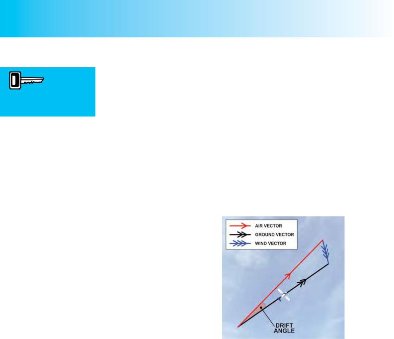
Figure 9.3, shows what will happen to an aircraft which is flying within a block of air which is, itself, moving. In this situation, unless the wind is an “exact” headwind or tailwind, the aircraft will not be proceeding over the ground in the direction in which its nose is pointing
but will be “drifting” away from that direction at a certain angle, called the drift angle.
In order to analyse this situation in more detail, we must ignore actual routes in terms of naming a starting point and destination, or considering distances, and simply consider the velocity of the aircraft and the velocity of the wind. If an aircraft sets off en-route, on a given heading, and at a given true airspeed, and is subject to a wind blowing across its track, that wind will cause the aircraft to follow (or, in pilot speech, to “make good”) a track across the ground which lies in a different direction from the direction in which the aircraft’s nose is pointing. The speed of the aircraft’s progress over the ground will also be different from the speed at which it is moving through the air: its true airspeed.
If we now construct a triangle which depicts only speed and direction (of the aircraft and wind), we have what is called a triangle of velocities.
127
Order: 6026
Customer: Oleg Ostapenko E-mail: ostapenko2002@yahoo.com
Customer: Oleg Ostapenko E-mail: ostapenko2002@yahoo.com
CHAPTER 9: PRINCIPLES OF DEAD RECKONING VISUAL AIR NAVIGATION
Velocity is a vector
quantity, involving
both magnitude (speed) and direction.
You should note that the term “velocity” refers both to direction and speed. In everyday speech, we tend to use the words speed and velocity as if they meant the same thing, but in science and mathematics (and the triangle of velocities belongs to the realms of both) the concepts of velocity and speed are different. Speed is defined by magnitude alone, for example, 90 knots, 167 kilometres per hour, or 104 miles per hour, whereas velocity involves both magnitude and direction, for example 90 knots due West, 104 miles per hour in a north-easterly direction, or 167 kilometres per hour in a direction of 245° True. In aviation, wind is always given as a velocity; 270°/20 knots, for instance, refers to a wind blowing from due West at 20 knots.
Let us, therefore, recreate the situation depicted in Figure 9.3, this time ignoring ground positions such as starting point, A, desired destination, B, and actual destination, C. Instead, we will construct a triangle of velocities, as illustrated in Figure 9.4.
In a triangle of velocities, the direction in which the lines are pointing (shown by the arrow heads) indicates direction of the aircraft and the wind in the real world, and the length of the lines represents the speed of the wind and of the aircraft. Direction and speed, considered together, give velocity.
In Figure 9.4, the red line marked with the single arrowhead represents the aircraft’s heading and true airspeed, the arrowhead indicating the direction in which the pilot is pointing the nose of the aircraft, and the length of the line (drawn to a given scale) representing the aircraft’s true airspeed. In a similar way, the length and direction of the blue line, marked with three arrowheads, represent the wind velocity, while the direction and length of the black line, marked with two arrowheads, represent respectively, the track along which the aircraft actually moves over the ground and the speed of the aircraft relative to the ground, the groundspeed. The angle between the red line and the black line is known as the drift angle.
The Air Vector, Wind Vector and
Ground Vector - Vector Addition.
Figure 9.4 A triangle of velocities represents direction and speed of the aircraft through the air, the wind speed and direction, and the track and speed of the aircraft over the ground.
In mathematics, each line representing the individual velocities is called a vector. The red line is the air vector. This vector, as we have seen, represents the path the aircraft follows relative to the block of air in which it is moving, and its speed through the air. By convention, the air vector is marked with a single arrowhead. The blue line, identified by convention with three arrow heads, is the wind vector, indicating the direction and speed of the block of air as it moves over the ground. The black line is the ground vector. The ground vector is conventionally marked by two arrowheads and, as already defined, indicates the track of the aircraft over the ground, and the aircraft’s groundspeed.
The triangle of velocities is, in fact, an illustration of what is known as vector addition.
128
ID: 3658
Customer: Oleg Ostapenko E-mail: ostapenko2002@yahoo.com
Customer: Oleg Ostapenko E-mail: ostapenko2002@yahoo.com
CHAPTER 9: PRINCIPLES OF DEAD RECKONING VISUAL AIR NAVIGATION
The wind vector is superimposed upon, or added to, the air vector in order to give the resultant ground vector, which is the vector which indicates how the aircraft actually moves relative to the ground over which it is flying.
When the triangle of velocities has been constructed to scale, we are able to measure the magnitude of the aircraft’s drift angle and the aircraft’s groundspeed.
The Drift Angle and Groundspeed.
Let us now look at a couple of practical examples of the triangle of velocities as applied to an aircraft flying at different speeds in a given wind.
The three sides of the triangle of velocities are:
•Heading / True Airspeed
•Track / Groundspeed
•Wind Velocity
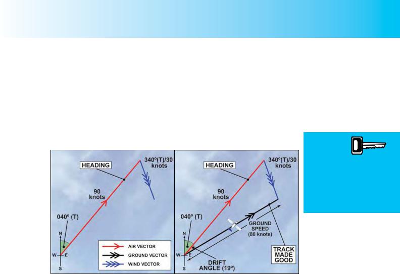
Figure 9.5a Figure 9.5b. Constructing a triangle of velocities.
In Figure 9.5 the true airspeed of the aircraft is assumed to be 90 knots. The aircraft is flying on a heading of 040°(T), while the speed of the wind is taken to be 30 knots, 340° (T). We construct the triangle of velocities to scale, and so angles represent directions and the lengths of the vectors represent speeds. The length of the air vector is three times the length of the wind vector, because the aircraft’s true airspeed is three times the speed of the wind. We construct the air vector and wind vector from the known bearings and speeds (Figure 9.5a) and, then, joining the open ends of the wind and air vectors, we draw a line to give us the resultant ground vector, as illustrated by Figure 9.5b. The angle between the air vector and the resulting ground vector gives us the angle of drift, and the length of the ground vector, gives the groundspeed.
Both graphically and mathematically, it is straightforward to calculate, for the above example, that the drift angle is 19° and the groundspeed is about 80 knots. Consequently, the aircraft is making good a track over the ground of 059° (T) at a groundspeed which is 10 knots slower than its true airspeed. You will learn how to carry out these calculations in Chapter 11, and from the CD-ROM on the navigation computer which accompanies this volume.
129
Order: 6026
Customer: Oleg Ostapenko E-mail: ostapenko2002@yahoo.com
Customer: Oleg Ostapenko E-mail: ostapenko2002@yahoo.com
CHAPTER 9: PRINCIPLES OF DEAD RECKONING VISUAL AIR NAVIGATION
The higher an aircraft’s
airspeed, the less drift it will
experience on any heading.
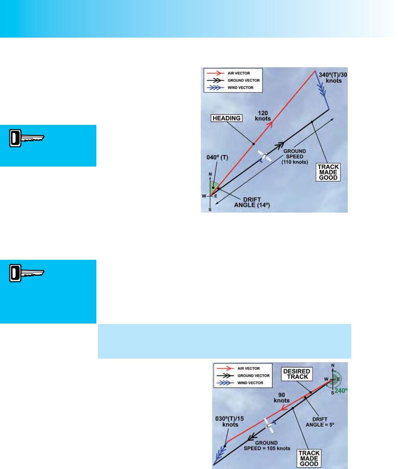
In Figure 9.6 the true airspeed of the aircraft is assumed to be 120 knots, on an identical heading to the first aircraft, of
040° (T), while the speed of the wind is still 30 knots, and still blowing from 340° (T). The length of the air vector must now be four times as long as the length of the wind vector, to represent the higher true airspeed of 120 knots, at which this aircraft is flying.
Figure 9.6 The higher the airspeed, the smaller the drift angle.
The amount of drift
experienced by an aircraft
in flight is a function of the aircraft’s true airspeed, its desired track and the speed and direction of the wind.
The Effect of True Airspeed on Drift Angle and Groundspeed.
You will see immediately from the triangle of velocities that, at the greater true airspeed, the angle of drift between the air vector and the ground vector is smaller than in Figure 9.5, while the length of the ground vector, representative of the groundspeed, is greater. By calculation, the drift angle is now only 14°, while the groundspeed is 110 knots. So this faster aircraft is making good a track of 054° (T) over the ground, at a groundspeed which is 10 knots slower than its true airspeed. The drift angle of the faster aircraft is smaller than that of the slower aircraft, because, in flying faster, it is deflected from its track by the wind by a smaller amount. However, because the wind is of the same strength (speed) and from the same direction in both cases, it has the same headwind component in both cases, and slows down both aircraft by the same margin of 10 knots.
We may conclude, then, that, for a given desired track, and for a given speed and direction of wind blowing across the aircraft’s desired track, an aircraft flying at a higher true airspeed will have a smaller angle of drift and a higher groundspeed.
If the crosswind has a headwind component as in Figures 9.5 and 9.6, the aircraft’s groundspeed will always be less than its true airspeed. Conversely, as depicted in Figure 9.7, if the crosswind has a tailwind component, the aircraft’s
groundspeed will always be greater than its true airspeed.
In Figure 9.7, the aircraft is flying a headingof240°(T)atatrueairspeed of 90 knots. The wind is from 030°
(T) with a strength of 15 knots. The aircraft is experiencing 5° of port drift and, therefore, making good a track over the ground of 235° (T).
Figure 9.7 With a tailwind component, groundspeed is always greater than true airspeed.
130
ID: 3658
Customer: Oleg Ostapenko E-mail: ostapenko2002@yahoo.com
Customer: Oleg Ostapenko E-mail: ostapenko2002@yahoo.com
CHAPTER 9: PRINCIPLES OF DEAD RECKONING VISUAL AIR NAVIGATION
And because there is a tailwind component on the heading it is flying, the aircraft’s groundspeed is almost 105 knots.
The Concept of Maximum Drift.
Following on from the situations analysed above, we should be able to deduce fairly easily, that a pilot can fly from A to B by pointing his aircraft along the direct track from A to B only if one of three conditions prevails during the planned flight: that there is absolutely no wind at all, or if the wind is a perfect headwind or tailwind.
If there is any crosswind element to the wind, the pilot must make allowance for wind when he sets his heading. The greater the crosswind element and the greater the windspeed, the greater will be with wind correction angle that the pilot needs to apply to make good his desired track.
At any given true airspeed, an aircraft will experience maximum drift when flying a track which puts the prevailing wind at 90° to that track. When the wind is directly on the nose or on the tail of his aircraft, there will be no drift, the effect of the wind being confined to modifying the aircraft’s achieved speed over the ground by a value equal to the windspeed. When blowing from intermediate quarters, the wind will cause the aircraft to drift at an angle which lies between 0° and the maximum drift angle.
Consequently, it is of practical interest to the pilot, to know what will be the maximum drift he is likely to experience when flying on different tracks at different true airspeeds.
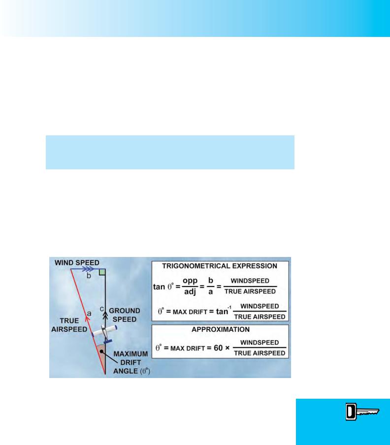
Figure 9.8 Calculating Maximum Drift when the wind is blowing at 90° to the aircraft’s track.
It can be shown that that for a given windspeed and aircraft true airspeed (TAS), approximate maximum drift in degrees is given by the following formula:
Approximate Maximum drift (°) = 60 × |
Windspeed (knots) |
|
TAS (knots) |
||
|
In practice, in order to find maximum drift, it is easier for a pilot to divide 60 by his planned TAS and multiply by the wind speed.
Max Drift º = 60 × Windspeed
True Airspeed
131
Order: 6026
Customer: Oleg Ostapenko E-mail: ostapenko2002@yahoo.com
Customer: Oleg Ostapenko E-mail: ostapenko2002@yahoo.com
CHAPTER 9: PRINCIPLES OF DEAD RECKONING VISUAL AIR NAVIGATION
So, on a day when the windspeed is 30 knots at your cruising altitude, if you have elected to fly at a TAS of 90 knots, the maximum drift your aircraft will experience is:
Maximum drift (°) = |
60 |
x 30 = 20° (or two thirds of the windspeed) |
90 |
If, on the same day, you were able to fly at a TAS of 120 knots, the maximum drift you would experience would be:
Maximum drift (°) = 12060 x 30 = 15° (or half the windspeed)
Using Maximum Drift in Mental Dead Reckoning Navigation When Airborne.
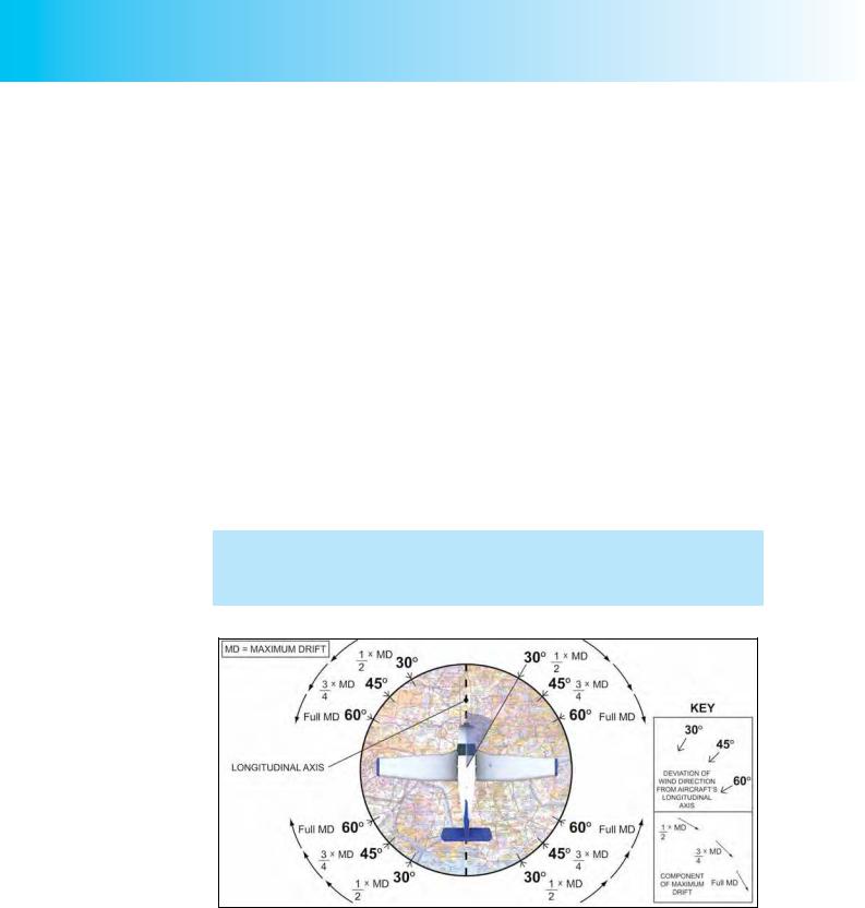
If you have to revise headings while airborne, it is worth knowing that you can estimate drift quite accurately using mental dead reckoning (MDR) techniques, by applying a “clock code” to the angle between the wind and track.
If, by pointing your aircraft’s nose along the new track, the wind will be blowing at an angle greater than 60° measured from the aircraft’s nose or tail, you will be experiencing, for all practical purposes, full maximum drift. At 30°, the wind will cause your aircraft to experience ½ maximum drift, and at 45° you will experience ¾ of the maximum drift. Similarly, 20º and 40º give 1/3 and 2/3 max drift
You will notice that the proportion of maximum drift that you experience for a wind blowing at a given angle to your desired track, is the same proportion that the value of the angle, expressed as minutes (time) instead of degrees, would have to one hour. (See Figure 9.9.)
Figure 9.9 Calculating component of maximum drift acting on an aircraft.
Note that this rule is an approximation only, but is good enough for visual navigation flights.
Let us assume that your aircraft is flying at a TAS of 90 knots on a day when the wind speed is 30 knots. As we have already calculated, the maximum drift you will experience in these conditions is 20°. The MDR “clock code” principle depicted in Figure 9.9 tells us that because 60 minutes is a complete hour, a wind blowing at
132

ID: 3658
Customer: Oleg Ostapenko E-mail: ostapenko2002@yahoo.com
Customer: Oleg Ostapenko E-mail: ostapenko2002@yahoo.com
CHAPTER 9: PRINCIPLES OF DEAD RECKONING VISUAL AIR NAVIGATION
60° to the desired track will cause the aircraft to be subjected to the full maximum drift of 20°. If the wind blows at 30° to the desired track the aircraft will experience ½ maximum drift, that is, 10°, by the reasoning that 30 minutes is half an hour. A wind at 15° to the desired track would cause the aircraft to drift at ¼ maximum drift, 5°, because 15 minutes is ¼ hour, and so on. The accurate calculation of the variation of the proportion of maximum drift with angle is again trigonometrical, based on the sine of the wind angle, but, again, our MDR “clock code” method gives results which are close enough for practical MDR navigation purposes.
This method of estimating drift is extremely useful to the pilot-navigator.
Calculating the Heading to Steer.
Now that we have covered the concept of the triangle of velocities, it is a fairly straightforward step to determine what heading we must steer, in a given wind, if we wish to fly along a desired track from A to B at a predetermined true airspeed.
Let us look at a few fundamental principles of how a pilot achieves his desired track, based on what we have learned so far.
•In order to follow a desired track, the pilot must steer a heading which will compensate for the wind. (Unless the wind is a perfect headwind or tailwind.)
•If the pilot points the nose of his aircraft along the desired track, any cross wind will always blow the aircraft from its desired track.
•The nose of the aircraft must, consequently, always be orientated into wind, by a greater or lesser extent. The wind will then blow the aircraft from its heading onto the desired track.
•The heading correction that a pilot applies to the aircraft’s heading in order to make good the desired track is equal to the value of the drift angle that the aircraft would experience if the pilot attempted to point its nose along the desired track.
We will examine this last point a little more closely, because it is fundamental to our pre-flight calculations when we plan to fly cross country.
From our study of the triangle of velocities, we have already seen that if a pilot attempts to head the aircraft directly along a desired track, with respect to which the wind has a crosswind component, his aircraft will drift from the desired track. The stronger the crosswind component and the slower the aircraft, the greater will be the drift angle.
As we have just stated, in order to set out along a desired track on a heading which will allow the aircraft to follow, or make good, that desired track, the pilot must modify the aircraft’s heading by pointing the nose of the aircraft into wind by a number of degrees equal to the drift the aircraft would experience if the pilot had set a heading directly along the desired track.
The magnitude of the heading correction that a pilot has to make will depend on the wind speed and direction and the true airspeed of the aircraft.
Wind blows an aircraft from Heading to Track.
133
Order: 6026
Customer: Oleg Ostapenko E-mail: ostapenko2002@yahoo.com
Customer: Oleg Ostapenko E-mail: ostapenko2002@yahoo.com
CHAPTER 9: PRINCIPLES OF DEAD RECKONING VISUAL AIR NAVIGATION
The theory of how the required heading correction is calculated is fairly straightforward and may easily be appreciated by looking again at the triangle of velocities.
Constructing a Triangle of Velocities to Determine the Heading to Fly.
We will construct a triangle of velocities similar to the ones earlier in this chapter which explained the phenomenon of drift. But, this time, in constructing the triangle of velocities, we will approach the task from the point of view of the pilot who, knowing the track he wishes to follow, the true airspeed at which he will fly, and the forecast wind, wishes to compensate for expected drift and calculate a heading to fly in order to make good the desired track.
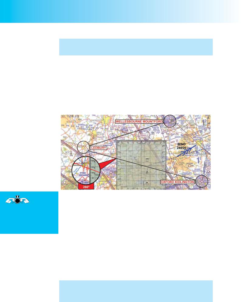
Let us assume that we are calculating a heading to fly for the first leg of a crosscountry flight from Oxford Kidlington to Wellesbourne Mountford, via Ledbury, for which we measured tracks and distances in Chapter 7. (See Figure 9.10.)
When


 preparing a
 navigation flight, always carry out gross
error checks to ensure that you have not misaligned the protractor or applied drift corrections in the wrong direction.
Figure 9.10 The first step in calculating the heading to fly for the leg Oxford Kidlington to Ledbury. True Track is 286º (T), True Airspeed will be 105 knots and the Forecast Wind is from 240º (T) at 20 knots.
We will further assume that our true airspeed from Oxford Kidlington to Ledbury will be 105 knots and that the forecast wind for that leg is from 240° (True) at 20 knots.
During the flight planning stage, the pilot should draw the forecast wind on his chart near the middle of his planned route so that he is able to retain a mental picture of the wind with respect to the desired track, throughout the flight. We already know that the heading we calculate will orientate our aircraft into wind, so if the true track we require is 286° (T) and the wind is from 240° (T), we can already see from the chart that the true heading we require is going to be less than 286° (T).
This type of initial mental calculation is a useful gross error check.
Let us now look at the triangle of velocities that we need to construct for the first leg of the route, in order to appreciate the theory of calculating the heading we need to fly to make good the desired track.
When you come to actually prepare a route for yourself, you will not have to construct a triangle of velocities, (though you could choose to do so if you wished). You will almost certainly be calculating the heading to fly using a navigation computer. (See Chapter 11).
134
ID: 3658
Customer: Oleg Ostapenko E-mail: ostapenko2002@yahoo.com
Customer: Oleg Ostapenko E-mail: ostapenko2002@yahoo.com
CHAPTER 9: PRINCIPLES OF DEAD RECKONING VISUAL AIR NAVIGATION
Figures 9.11a, 9.11b and 9.11c depict the three stages in the construction of the triangle of velocities.
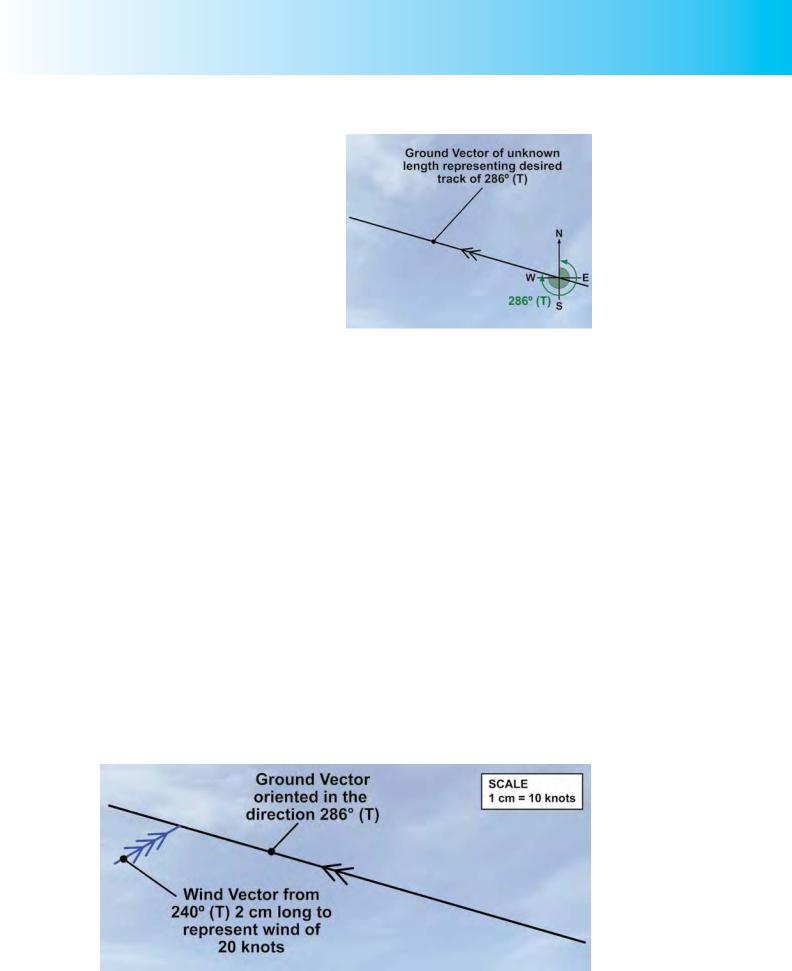
Drawing in the Ground Vector.
In Figure 9.11a, we have simply drawn a line in the direction of the true track. This line is to be our ground vector; it is the track we must make good so we already know its direction: 286°
(T). When the triangle of velocities is complete, the length of the ground vector will give us our ground speed, but we do not yet know how long the line will be. However, as this line is the ground vector, we may already mark it with two arrowheads.
Drawing in the Wind Vector.
Figure 9.11a We wish to calculate the heading to fly for the leg Oxford, Kidlington, to Ledbury True Track is 286° (T), True Airspeed will be 105 knots and the Forecast Wind is from 240°
(T) at 20 knots.
In Figure 9.11b, we have added the wind vector to the triangle of velocities that we are constructing. For the wind vector, we have information on both direction and speed which we have obtained from the forecaster or from documentation such as
Met Office Form 214, the Spot Wind Chart. The wind is blowing from 240° (T) at 20 knots, so for the wind vector we can draw in a line of known direction and known length.
We must take care at this point, though, to make a sensible choice of scale with which we can represent speed by length. We decide to use the scale 1cm = 10 knots. We can choose any scale we wish but we have to think of practical lengths, and when we mark off our true airspeed of 105 knots, we will need to draw a line of 10.5 cm using the scale we have chosen. So 1 cm to 10 knots seems about right, in order that we can keep our lines on the paper that we have at our disposal.
Remember that the wind will always blow the aircraft from the heading we are going to calculate onto the desired track. (That is why to achieve the desired track we always have to point the nose of the aircraft into wind.) Consequently, in the triangle of velocities, the wind vector points towards the ground vector. We draw in the wind vector at any point along the ground vector with a direction of 240°(T) and 2 cm long to represent 20 knots.
Figure 9.11b Drawing in the Wind Vector.
135
Order: 6026
Customer: Oleg Ostapenko E-mail: ostapenko2002@yahoo.com
Customer: Oleg Ostapenko E-mail: ostapenko2002@yahoo.com
CHAPTER 9: PRINCIPLES OF DEAD RECKONING VISUAL AIR NAVIGATION
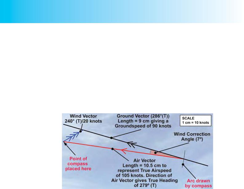
Completing the Triangle of Velocities: The Air Vector and Ground Vector.
In Figure 9.11c, we complete the triangle of velocities to obtain the heading to steer and the groundspeed, by drawing in the air vector. We do not know the direction of the air vector; that will be the heading that we are trying to find. But we do know that its length must represent our planned true airspeed of 105 knots.
On the scale we have chosen, this length will be 10.5 cm. We, therefore, take a pair of compasses and set the point and pencil tip 10.5 cm apart. Placing the point of the compasses at the end of the wind vector, 2 cm from its origin, we inscribe a short arc to intersect the ground vector. The point at which the arc intersects the ground vector allows us to complete our triangle of velocities, so we draw in the air vector to join the end of the wind vector and the point at which the arc intersects the ground vector, at 10.5 cm distance.
Figure 9.11c Constructing the Air Vector to determine True Heading, and establishing the length of the Ground Vector to obtain Groundspeed.
The direction of the air vector now gives us the true heading that we must steer, at 105 knots true airspeed, to make good our desired track of 286° (T).
The angle between the air vector and the ground vector (which represents the direction of our desired track) is the wind correction angle that we must apply to the desired track angle in order to obtain the true heading.
If we wish, we can measure the wind correction angle directly from the triangle of velocities, as the triangle has been drawn to scale, or we can calculate the heading using trigonometry. Whichever method we use, we will find that the wind correction angle is 7° and the heading to steer is 279° (T).
We also now have a length for the ground vector. This is 9 cm which tells us that our groundspeed along our desired track will be 90 knots. We, of course, expect our groundspeed to be less than the airspeed because the wind on this leg has a headwind component.
That completes the theory of how a heading is calculated to make good a desired track at a planned true airspeed, and for a given wind strength and direction. Everything we need to calculate may be worked out by considering velocities; that is, speeds and directions.
136