

ppl_03_e2
.pdfID: 3658
Customer: Oleg Ostapenko E-mail: ostapenko2002@yahoo.com
Customer: Oleg Ostapenko E-mail: ostapenko2002@yahoo.com CHAPTER 2: TIME QUESTIONS
Representative PPL - type questions to test your theoretical knowledge of Time.
1.What is the ICAO definition of night?
a.From half an hour after sunset to half an hour before sunrise
b.The period between the end of evening civil twilight and the beginning of morning civil twilight, or such other period between sunset and sunrise as may be described by the appropriate authority
c.From sunset to sunrise
d.Any period decided upon by a national aviation authority
2.What is the United Kingdom Civil Aviation Authority’s definition of night?
a.From half an hour after sunset to half an hour before sunrise
b.The period between the end of evening civil twilight and the beginning of morning civil twilight, or such other period between sunset and sunrise as may be described by the appropriate authority
c.From sunset to sunrise
d.Any period decided upon by a national aviation authority
3.Which of the following statements is correct?
a.Flight at night in accordance with the Visual Flight Rules is not permitted in the United Kingdom
b.Flight at night in accordance with the Visual Flight Rules is permitted in the United Kingdom, but only in VMC
c.Flight at night in accordance with the Visual Flight Rules is permitted in the United Kingdom, but only if the pilot holds a valid Instrument Rating
d.Flight at night in accordance with the Visual Flight Rules is permitted in the United Kingdom, but only if the pilot holds a valid Instrument Rating or IMC Rating
4.What is the cause of annual seasonal change on the Earth and the changing lengths of the periods of daylight and darkness throughout the year?
a.The fact that the Earth completes one rotation on its axis in 24 hours
b.The tilt of the Earths axis at 23½° to its orbital plane and the fact that the Earth spins on its own axis
c.The fact that the Earth completes one orbit of the Sun every 365.2422 days
d.The tilt of the Earths axis at 66½° to its orbital plane, the fact that the Earth completes one rotation on its axis in 24 hours, and one orbit of the sun every 365.2422 days
27

Order: 6026
Customer: Oleg Ostapenko E-mail: ostapenko2002@yahoo.com
Customer: Oleg Ostapenko E-mail: ostapenko2002@yahoo.com
CHAPTER 2: TIME QUESTIONS
5.What determines the local mean time of sunrise and sunset at any location on Earth?
a.The time of year and the longitude and elevation of the location
b.The time of year only
c.The time of year, the location’s latitude and the elevation of the location
d.The latitude only
6.Which of the following statements is correct?
a.At any given spot on Earth, the Sun will sink below the horizon earlier at sea-level than at altitude
b.Sunrise and sunset will occur at the same local mean time at all locations of the same elevation along a given meridian of longitude
c.At any given spot on Earth, the Sun will sink below the horizon later at sea-level than at altitude
d.The local mean time of sunrise and sunset at any location along a parallel of latitude is independent of elevation
Question |
1 |
2 |
3 |
4 |
5 |
6 |
|
|
|
|
|
|
|
Answer |
|
|
|
|
|
|
The answers to these questions can be found at the end of this book.
28
Customer: Oleg Ostapenko E-mail: ostapenko2002@yahoo.com
CHAPTER 3
DIRECTION
29

Order: 6026
Customer: Oleg Ostapenko E-mail: ostapenko2002@yahoo.com
Customer: Oleg Ostapenko E-mail: ostapenko2002@yahoo.com
CHAPTER 3: DIRECTION
30

ID: 3658
Customer: Oleg Ostapenko E-mail: ostapenko2002@yahoo.com Customer: Oleg Ostapenko E-mail: ostapenko2002@yahoo.com
CHAPTER 3: DIRECTION
INTRODUCTION.
In Chapter One, you learned that position is determined on the Earth by reference to latitude and longitude. For instance, the location of Madrid, the capital of Spain, is defined as 43° 23’ North, 3° 43’ West. Meridians of longitude run between the Earth’s Geographic North and South Poles and the parallels of latitude, running East and West, lie at 90° to the meridians of longitude.
Directions which are referenced to the Earth’s geographical poles are known as true directions.
The grid lines on aeronautical charts which run between North and South, and East and West, represent, respectively, the meridians of longitude and parallels of latitude; therefore, the North, South, East and West directions represented by the grid lines are true directions. The 1:500 000 aeronautical chart is a Lambert Conformal Conic Projection so the lines of longitude on this chart converge as they extend towards the pole. Over a small surface area, however, such as that represented by each individual chart, this convergence is negligible.
When a pilot is planning a navigation flight, he draws a straight line on his chart to represent the track along which he wishes to fly and, using a navigation protractor, measures the bearing of the track line as being between 0° and 359° from North, as represented by the vertical grid lines. The bearing of the track that the pilot wishes to fly is, therefore, given as a bearing with respect to True North. Such a bearing
is called a true bearing.
Figure 3.1 The 1:500 000 Chart. Meridians of longitude converge towards the geographical pole. A straight line is a great circle.
A straight line joining two locations on the 1:500 000 aeronautical chart, Figure 3.1, represents a great circle on the surface of the Earth, being the shortest distance between the two points. So the straight line actually cuts the meridians of longitude at a slightly different angle. That is why it is good practice to measure a bearing at or near the mid point of track. (See Figure 3.1.) Over short distances of less than about 200 nautical miles, however, any variation in angle is negligible.
So, if a pilot was planning to fly from Oxford Airport to Wellesbourne Mountford via Ledbury, he would find, after drawing his desired tracks on the chart, that the first leg of his required track, from Oxford to Ledbury, was 286° True while the second leg, from Ledbury to Wellesbourne Mountford, was 072° True. (See Figure 3.2a and
Figure 3.2b.)
31

Order: 6026
Customer: Oleg Ostapenko E-mail: ostapenko2002@yahoo.com
Customer: Oleg Ostapenko E-mail: ostapenko2002@yahoo.com
CHAPTER 3: DIRECTION
Figure 3.2a Measuring the true bearing of a track line from Oxford aerodrome to Ledbury.
Figure 3.2b Measuring the true bearing of a track line from Ledbury to Wellesbourne Mountford.
In summary, the bearing of any track line drawn on a chart measured with respect to the chart’s vertical grid lines is a true bearing referenced to True (Geographic) North.
The Direct Indicating
Magnetic
Compass is usually the main magnetic heading reference in light aircraft.
TRUE NORTH AND MAGNETIC NORTH.
However, the magnetic compass, the primary direction finding instrument used by the pilot-navigator of a light aircraft does not indicate True North. The heading information given by an aircraft’s magnetic compass is not referenced to True (Geographic) North but to Magnetic North. So, if an aircraft’s compass indicated that the aircraft was heading in a direction of, say, 270°, that heading would not be 270° True (which would be due West) but 270° Magnetic, which is quite another thing.
It is of the greatest importance in navigation that the difference between true indications and magnetic indications of direction should always be allowed for.
32

ID: 3658
Customer: Oleg Ostapenko E-mail: ostapenko2002@yahoo.com Customer: Oleg Ostapenko E-mail: ostapenko2002@yahoo.com
CHAPTER 3: DIRECTION
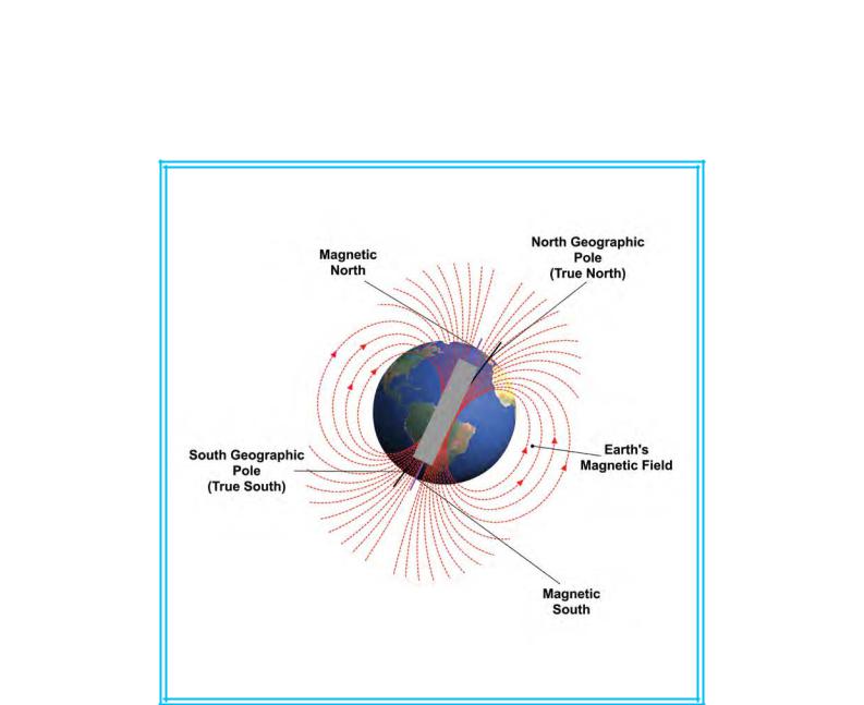
Magnetic North is quite a different concept from True (Geographic) North. The Earth acts as if a giant magnet passes through its centre, whose axis lies at an angle to the line joining the Earth’s North and South Geographical Poles ( i.e. the Earth’s spin axis), as depicted in Figure 3.3.
Figure 3.3 The Earth’s Magnetic Poles do not coincide with its Geographical North and South Poles.
Because of the angle between the axis of the imaginary magnet and the Earth’s spin axis, the poles of the imaginary Earth magnet do not coincide with the Geographical North and South Poles. The Canadian Geological Survey estimates that the 2005 position of the Earth’s North Magnetic Pole was 82.7° North, 114.4° West, to the west of Ellesmere Island, the biggest of the Queen Elizabeth Islands in Canada. The Magnetic South Pole’s estimated 2005 position was at 64.7° South, 138° East. The magnetic poles wander around significantly, and so extrapolation of their previous positions in order to predict future positions is not easy.
Because of the magnetic properties of the Earth, a magnetic field, also depicted in
Figure 3.3, surrounds the planet. Under the influence of this magnetic field, the north-seeking end of the needle of a magnetic compass indicates the direction of Magnetic North.
33

Order: 6026
Magnetic Variation is
the angle between True North and Magnetic
North, and can be East or West of True North.
At any point on the Earth’s surface, the angular difference between Magnetic North, indicated by a compass needle, and the direction of True (Geographic) North is called magnetic variation. The angle of magnetic variation is different in different locations on the surface of the Earth, as illustrated in Figure 3.4.
Furthermore, again depending on where on the Earth’s surface a compass reading is taken, Magnetic North may lie either to the West, South or to the East of True North. (See Figure 3.5.) Magnetic variation may range from 0° to 180° East or West of True North.
As we have mentioned, the Earth’s magnetic poles are wandering constantly, and so magnetic variation changes not only with location on the Earth’s surface but also with time. The North Magnetic Pole is currently moving at a rate of more than 22 nautical miles per year. Its rate of movement has varied considerably since records began, in 1831. The Geological Survey of Canada keeps track of the North Magnetic Pole, by periodically carrying out magnetic surveys to redetermine the Pole’s location.
Across the British Isles, magnetic variation currently (July 2010) ranges from about 7° West, to the West of Northern Ireland, to 1° West, off the East Anglian coast. In the British
Isles, magnetic variation is changing (decreasing) at the rate of about 7’ per year (i.e. 1° in about 8 years).
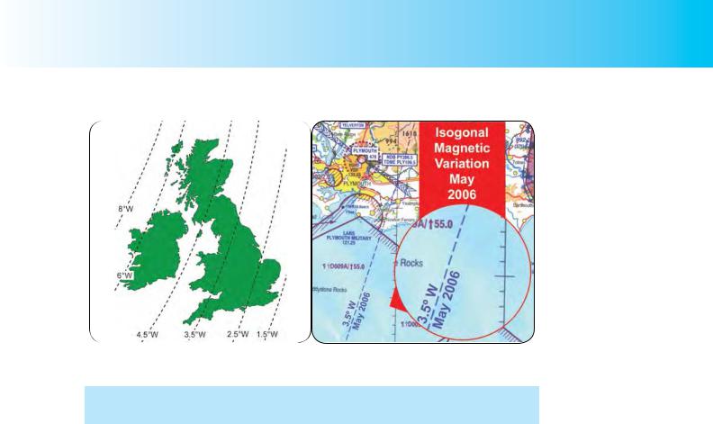
Isogonals and Agonic Lines.
On aeronautical charts, locations on the Earth’s surface which have the same magnetic variation are joined by lines called isogonals. Figure 3.6a depicts representative isogonals lying across the British Isles in early 2007. Figure 3.6b shows the isogonal, just to the East of Plymouth, which, in 2006, joined points in the United Kingdom where the magnetic variation was 3.5° West.
34
ID: 3658
Customer: Oleg Ostapenko E-mail: ostapenko2002@yahoo.com Customer: Oleg Ostapenko E-mail: ostapenko2002@yahoo.com
CHAPTER 3: DIRECTION
Figure 3.6a Representative isogonal across the British Isles in early 2007.
Figure 3.6b The isogonal 3.5° West, to the East of Plymouth, England, May 2006.
Isogonals which indicate a magnetic variation of zero degrees (i.e. where Magnetic North is in the same direction as True North) are called agonic lines.
MAGNETIC HEADING.
As we mentioned above, when a pilot is planning a cross-country flight, he draws the track lines he wishes to fly along on an aeronautical chart and measures the bearing of each track with reference to the vertical grid lines marked on the chart. You have already learned that these vertical lines represent meridians of longitude, and a bearing measured from one of these lines, at the mid-track position, will give the heading of the desired track, with reference to True North.
But, as we have learned, once in the air, the instrument on which a pilot relies to give him the heading to steer is the magnetic compass, and compass headings are referenced to Magnetic North not True North.
What action, then, must a pilot take to convert the true heading that he has measured from the chart into a heading that he can steer, once airborne, using the indications of his compass?
The answer to this question is that the pilot must convert the true headings into magnetic headings. It is crucial that the pilot-navigator should understand that this is so. It does not matter that, once in the air, he may use the gyroscopic Direction Indicator to steer headings; the Direction Indicator (DI) is aligned to the magnetic compass, so the DI readings are referenced to Magnetic North, too.
Let us return to our example of the planned flight from Oxford Airport to Wellesbourne Mountford via Ledbury, to illustrate how to determine the magnetic headings that a pilot must fly when airborne. For the time being we will ignore the effect of wind on our planned headings. You will learn how to allow for wind in later chapters.
We have already seen that the first leg of the flight from Oxford to Ledbury requires us to fly a true heading of 286°(T). (We will add (T) or (M) to heading information to make clear the distinction between true and magnetic headings.)
35

Order: 6026
Customer: Oleg Ostapenko E-mail: ostapenko2002@yahoo.com
Customer: Oleg Ostapenko E-mail: ostapenko2002@yahoo.com
CHAPTER 3: DIRECTION
Figure 3.7a The Heading of 286° (T). |
Figure 3.7b Magnetic North, here, lies 3° to |
|
the West of True North. |
Now, we know that 286°(T) is referenced to True North. This is depicted in Figure 3.7a. In order to find the magnetic heading, we must determine the value of magnetic variation for the region in which the flight is to take place. You will recall that the magnetic variation for a given region is the difference, measured in degrees, between the direction of True North, in that region, and the direction of Magnetic North. Referring to our aeronautical chart, we see that our route lies between the two isogonals, 2.5° West and 3.5° West (for mid-2006). It is a reasonable assumption, then, that 3° West will be a fairly accurate magnetic variation to apply to our heading calculations.
We have determined, then, that, in our region, Magnetic North lies 3° to the West of
True North. This is depicted in Figure 3.7b.
Considering the situation for a few moments (see Figure 3.7c), we realise that in, our case, in order to make good our desired track, we must add the magnetic variation of 3° West to the true heading of 286°(T) that we have measured, and fly a magnetic heading of 289° (M).
Figure 3.7c Magnetic Variation is 3° West. We add this to our True Heading of 286° (T) to obtain a Magnetic Heading of
289° (M).
Figure 3.7d If Magnetic North lay to the East of True North we would subtract
Magnetic Variation from True Heading to obtain the Magnetic Heading.
36