

Diss / 10
.pdfDigital Interperiod Signal Processing Algorithms |
103 |
where
α = βi − βtg ϕ0
and
1 |
|
|
ˆ |
|
|
|
||
|
|
|
|
|
||||
|
dg(θ0 ± θ tg ) |
|
|
|
||||
χ = |
|
|
|
|
|
|
|
. |
g(θ0 ) |
|
|
dθtg |
|
ˆ |
|||
From (3.150), taking into consideration (3.151), we obtain |
|
θ tg = θ0 |
|
|||||
|
|
|
||||||
|
ˆ |
|
|
π1 − π2 |
|
|
|
|
|
θtg = − |
|
. |
|
|
|
||
|
2nq0χ |
|
|
|
||||
3.4.4 Doppler Frequency Measurer
(3.152)
(3.153)
(3.154)
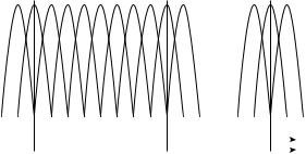
In complex coherent pulse radar systems, the multiple-channel filters are used to measure the Doppler frequency (see Figure 3.21a). The number n of frequency channels with the preliminary filters possessing the overlapping amplitude–frequency characteristics and DGDs has been provided (see Figure 3.21b). The required number of frequency channels is defined by the following formula:
n = |
2 fDmax |
, |
(3.155) |
||
|
|||||
|
δfD |
|
|||
fDmax |
= ± |
2Vtgmax |
(3.156) |
||
λ |
|||||
|
|
|
|||
where
fDmax is the Doppler frequency range, which is subjected to measure, defined by the well-known relationship
λis the position number with respect to the direction selected as the origin and the first pulse of the target return pulse train is fixed on this position by the criterion of l from m(l/m)
δfD is the CRS resolution by Doppler frequency that is characterized by a spread of signal ambiguity body section along the axis f [35]
|
|
|
|
|
|
|
|
|
|
|
|
H( f ) |
δfD |
|
|
|
|||
|
|
|
|
|
|
|
|
|
|
|
|
||||||||
|
|
|
RF1 |
|
|
DGD1 |
|
|
Making- |
f^D |
|
|
|
|
|
|
|
|
|
|
|
|
|
|
|
|
|
|
|
|
|
|
|
|
|||||
|
|
|
|
|
|
|
|
|
|
|
|
|
|
|
|
|
|||
|
|
|
RF2x(t) |
|
|
|
|
|
|
|
|
|
|||||||
|
|
|
|
|
DGD2 |
|
|
decision |
|
|
|
|
|
|
|
|
|
|
|
|
|
|
|
|
|
|
|
|
|
|
|
|
|
|
|
|
|||
|
|
|
|
. |
|
|
. |
|
device |
|
|
|
|
|
|
|
|
|
|
|
|
|
|
|
|
|
|
|
|
|
|
|
|
|
|||||
|
. |
|
. |
|
|
|
|
|
|
|
|
|
|
|
|
||||
|
. |
|
. |
|
|
|
|
|
|
|
|
|
|
|
|
||||
|
|
|
RFN |
|
|
DGDN |
|
|
|
|
|
|
|
|
|
|
|
|
f |
|
|
|
|
|
|
|
|
|
|
|
|
|
|
|
|
|
|||
|
|
|
|
|
|
|
|
|
|
|
|
|
|
|
|
|
|
|
|
(a) |
|
|
|
|
|
(b) |
|
|
|
|
|||||||||
|
|
|
|
|
|
|
|
|
|||||||||||
FIGURE 3.21 (a) Doppler frequency measuring by multiple channel filters and (b) amplitude–frequency responses of filters.
104 |
|
|
|
|
|
|
|
|
|
|
Signal Processing in Radar Systems |
||
7 |
0 |
1 |
2 |
3 |
4 |
5 |
6 |
7 |
0 |
1 |
7 |
0 |
1 |
. . .
0 |
1/T |
2/T |
f |
|
|
|
|
|
V |
0 |
Vtg1 |
Vtg2 |
||
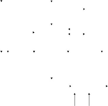
FIGURE 3.22 Amplitude–frequency responses of spectrum analyzer constructed based on DFT, N = 0.
Rough estimation of the Doppler frequency fD can be defined by the channel number with the maximal amplitude of voltage at the measurer output. To increase the accuracy of definition of the Doppler frequency fD estimation we can use the output amplitudes of three frequency channels. In this case, a position of the parabolic amplitude envelope of selected frequency channels is considered as the estimation of the Doppler frequency fD.
Realization in the time domain of the considered filter multiple-channel network is a very difficult problem. For this reason, a realization of the considered filter multiple-channel network in frequency domain based on DFT is of prime interest for us. As well known, the presence of specific spectral characteristic distortions caused by limitation in the sample size N of the input target return signal is a peculiarity of DFT. As a result, the band-pass filter with the central frequency
fk = |
k |
, k = 0,1,…, N − 1 |
(3.157) |
|
NT |
||||
|
|
|
must correspond to each DFT coefficient. The bandwidth of each filter is equal to N−1. A set of the main lobes of the spectrum analyzer amplitude–frequency response designed and constructed based on DFT at N = 8 are shown in Figure 3.22. Thus, the spectral analyzer designed and constructed based on DFT can be presented as a set of narrowband filters, each of which is the matched filter for sinusoidal signal with frequency matched with the filter central frequency.
The considered features of DFT allow us to employ the corresponding multiple-channel filters to accumulate the coherent target return signals separately in each of N obtained frequency channels. In this case, a detection and estimation of the Doppler frequency of the target return signal is carried out by the number of DFT channels, in which the accumulated signal has exceeded the threshold of detection. If the threshold of detection has been exceeded in several frequency channels, we must make averaging or weight union of frequency estimations of the Doppler frequency. To determine the DFT coefficients, the fast DFT (FDFT) algorithms are used, which allows us to solve the considered problem in real time.
Presence of side lobes in the equivalent amplitude–frequency characteristics of spectral analyzer filters leads us to spectrum splatter (frequency harmonics), and an overlapping of the main lobes forms an incidental amplitude modulation of spectrum. To attenuate the first phenomenon, the specific weight functions called “windows” are used. In using the “window,” DFT takes the following form:
N −1 |
|
|
j2πik |
|
||
|
|
|
||||
Fuw[k] = ∑w[i]u[i]exp |
− |
|
, |
(3.158) |
||
N |
||||||
i= 0 |
|
|
|
|
||
|
|
|
|
|
||
Digital Interperiod Signal Processing Algorithms |
105 |
where |
|
w[i] = w[iT ], i = 0,1, 2,…, N − 1 |
(3.159) |
is the weight “window” function. In the case of the rectangle weight function, which corresponds practically to DFT of N input signals (the target return signals) without weighting, the side lobes of equivalent amplitude–frequency response of filters are maximal, approximately for about −13 dB. For this reason, as a rule, the “windows” with dropping weight coefficients, for example, triangle, cosine, Gauss, Dolph–Chebyshev, Hamming, and so on, are used.
Under the Doppler frequency estimation, the signal sample size N for DFT is selected to ensure the required spectral resolution
δf = |
ν |
, |
(3.160) |
|
TN |
||||
|
|
|
where ν is the coefficient characterizing a spectral bandwidth increase for the selected “window .” As a rule, the value of ν is selected equal to an equivalent noise bandwidth of the “window,” that is,
ν = |
|
∑N −1 w2[iT ] |
|
||
|
i= 0 |
|
. |
(3.161) |
|
|
N −1 |
2 |
|||
|
|
∑i= 0 |
w[iT ] |
|
|
|
|
|
|
||
The incidental amplitude modulation of spectrum leads us to additional losses under signal processing of the target return pulse train, the Doppler frequency of which does not coincide with basic frequencies multiple to the frequency 1/TN. The losses caused by the incidental amplitude modulation of spectrum are for about 1/2 dB in the case of “windows” with smoothly dropping weight coefficients. Maximal losses under DFT caused by maximal losses owing to the incidental amplitude modulation of spectrum for the given “window” and DFT losses caused by a shape of the given “window” do not exceed 3 ÷ 4 dB.
3.5 COMPLEX GENERALIZED ALGORITHMS OF DIGITAL INTERPERIOD SIGNAL PROCESSING
The complex digital generalized interperiod signal processing/detection algorithm employed by CRSs is offered as a solution to the following problems:
•To detect the target return signals
•To measure the parameters of target return signals
•To form and estimate the current coordinates, parameters, and features of targets by information contained in the target return signals
•To code the coordinates and parameters of targets and process them for follow-up processing
The complex digital generalized interperiod signal processing/detection algorithm is synthesized by the composition of particular digital interperiod signal processing/detection algorithms. There are many ways for the composition of the particular digital interperiod signal processing/detection algorithms. The number and content of construction ways of the complex digital generalized interperiod signal processing/detection algorithm depends on the operation
106 |
Signal Processing in Radar Systems |
conditions of CRSs. At the same time, there is a need to keep in mind that at any condition the CRS operates in very hard noise environment caused by deliberate interferences (active or passive) in conflict situations; reflections from ground objects (buildings, trees, vehicles, mountains, etc.) and atmospheric precipitation (rain, snow, fog, clouds); reflection from nonmechanical objects in atmosphere; and nonsynchronized (chaotic) pulse noise and interference. For this reason, the main problem that is solved in the course of designing the complex digital generalized interperiod signal processing/detection algorithm is the problem of compensation of background and scattering returns and the problem of stabilization of the probability of false
alarm PF.
While designing the complex digital generalized interperiod signal processing/detection algorithm it is appropriate to proceed from the assumption that, in each specific case of radar system operation, a definite noise environment requiring reconstruction or retuning of the considered algorithm to ensure a qualitative receiving and processing the target return signals at the fixed probability of false alarm PF will be formed all over the radar coverage or in individual parts of radar coverage. Whereas the number of such situations is very high, we can call several most specific cases:
•Signal processing/detection in Gaussian uncorrelated (or weakly correlated) noise with unknown variance
•Signal processing/detection in Gaussian uncorrelated (or weakly correlated) noise with unknown variance plus chaotic pulse interference
•Signal processing/detection in non-Gaussian noise, for example, while using the intraperiod nonlinear signal processing/detection algorithms (limiters, logarithmic amplifiers, and so on)
•Signal processing/detection in correlated Gaussian noise with high variance by value
Under such an approach, naturally, it is required to include the adaptive generalized signal processing/detection algorithms for various noise situations and specific algorithms, which are able to recognize the type of situation and make a decision, into the complex digital generalized interperiod signal processing/detection algorithm. The algorithms recognizing specific situations can be presented in the form of individual signal processing subsystems. Finally, there is a need to provide for a high-speed switchboard in the content of the complex digital generalized interperiod signal processing/detection algorithm, which allows us to carry out all necessary switching in the course of adaptation to noise environment.
Thus, the complex digital generalized interperiod signal processing/detection algorithm for CRSs must be tuned by the totality of a given set of situations and be adaptive to noise level. The simplest version of the complex digital generalized interperiod signal processing/detection algorithm is shown in Figure 3.23. The subsystem of intraperiod signal processing, the output signals of which are the input signals for the considered complex digital generalized interperiod signal processing/detection algorithm, and the subsystem of environment analysis, the output signals of which are meant for the reconstruction of complex digital generalized interperiod signal processing/detection algorithm, are presented in Figure 3.23 by individual blocks. The following digital signal processing/detection subsystems can be produced by the considered diagram in Figure 3.23:
•Digital signal processing and detection subsystem for slowly moving targets and targets moving with blind velocities. The blocks 3, 5, 6, 10, and 11 form this subsystem. The block 3 carries out the generation, averaging, and storing of the noise envelope amplitudes for all resolution elements of the CRS. The block 6 generates the thresholds to detect the target return signals at the zero channel output of FDFT filter (the block 5) using the noise
Digital Interperiod Signal Processing Algorithms |
|
|
|
|
|
|
|
107 |
|||||||||||||||||||||||||
|
|
|
|
|
|
|
|
|
|
|
|
|
|
|
|
|
|
|
|
|
|
|
|
|
|
|
|
|
|
|
|
|
|
|
Environment |
|
|
|
|
|
|
|
|
Intraperiod sig- |
|
|
|
|
|
|
|
|
|
|
|
|
|
|
|
|
|||||||
|
analysis |
|
|
|
|
|
|
|
|
nal processing |
|
|
|
|
|
|
|
|
|
|
|
|
|
|
|
|
|||||||
|
subsystem |
|
|
|
|
|
|
|
|
|
|
subsystem |
|
|
|
|
|
|
|
|
|
|
|
|
|
|
|
|
|||||
|
|
|
|
|
|
|
|
|
|
|
|
|
|
|
|
|
|
|
|
|
|
|
|
|
|
|
|
|
|
|
|
|
|
3 |
|
|
|
1 |
|
|
|
|
|
|
|
|
|
|
|
|
4 |
|
|
|
|
|
|
||||||||||
|
|
|
|
|
|
|
|
|
|
|
|
|
|
|
|
|
|
|
|
|
|||||||||||||
|
Noise map |
|
|
|
|
|
|
|
|
|
Input signal |
|
|
|
|
|
|
|
|
|
Moving-target |
|
|||||||||||
|
forming |
|
|
|
|
|
|
|
|
|
|
|
memory |
|
|
|
|
|
|
|
|
|
indicator |
|
|||||||||
|
algorithm |
|
|
|
|
|
|
|
|
|
|
|
device |
|
|
|
|
|
|
|
|
|
algorithm |
|
|||||||||
|
|
|
|
|
2 |
|
|
|
|
|
|
|
|
|
|
|
|
|
|
5 |
|
|
|
|
|
|
|||||||
|
|
|
|
|
|
|
|
|
|
|
|
|
|
|
|
|
|
|
|
|
|
|
|
|
|||||||||
|
|
|
|
|
|
|
|
|
|
|
|
|
Operations |
|
|
|
|
|
|
|
|
|
|
|
FFT |
|
|
||||||
|
|
|
|
|
|
|
|
|
|
|
|
|
|
|
|
|
|
|
|
|
|
|
|
|
|
||||||||
|
|
|
|
|
|
|
|
|
|
|
|
commutator |
|
|
|
|
|
|
|
|
|
|
|
|
|||||||||
|
|
|
|
|
|
|
|
|
|
|
|
|
|
|
|
|
|
|
|
|
|
|
|
|
|||||||||
|
|
|
|
|
|
|
|
|
|
|
|
|
|
|
|
|
|
|
|
|
|
|
|
|
|
|
|
||||||
|
|
|
|
|
|
|
|
|
|
|
|
|
|
|
|
|
|
|
|
|
|
|
|
|
|
|
|
|
|
||||
|
|
|
|
|
|
|
|
|
|
|
|
|
|
|
|
|
|
|
|
|
|
|
|
|
|
|
|
|
|||||
|
|
|
|
|
|
|
|
|
|
|
|
|
|
|
|
|
|
|
|
|
|
|
|
|
|
|
|
|
|
|
|
|
|
6 |
|
|
7 |
|
|
|
|
|
|
8 |
|
|
|
|
|
|
|
9 |
|
|
|
|
|
||||||||||
|
|
|
|
|
|
|
|
|
|
|
|
|
|
|
|
|
|
|
|||||||||||||||
|
Detection of |
|
|
Adaptive non |
|
|
|
|
Nonparametric |
|
|
|
|
Adaptive |
|
||||||||||||||||||
|
targets with |
|
|
coherent signal |
|
|
|
signal |
|
|
|
coherent signal |
|
||||||||||||||||||||
|
zero velocity |
|
|
processing |
|
|
|
|
|
processing |
|
|
|
|
processing |
|
|||||||||||||||||
|
|
|
|
|
|
|
|
|
|
|
|
|
|
|
|
|
|
|
|
|
|
|
|
|
|
|
|
|
|||||
|
|
|
|
9 |
|
|
|
|
|
10 |
|
|
|
|
|
|
|
|
|
|
|||||||||||||
|
|
|
|
|
|
|
|
|
|
|
|
|
|
|
|
|
|
||||||||||||||||
|
|
|
|
|
|
|
|
|
|
|
|
Radar target |
|
|
|
|
|
|
Coordinate |
|
|
|
|
|
|||||||||
|
|
|
|
|
|
|
|
|
|
|
|
|
|
|
forming |
|
|
|
|
|
|
coding |
|
|
|
|
|
||||||
|
|
|
|
|
|
|
|
|
|
|
|
|
|
|
|
|
|
|
|
|
|
|
|
|
|
|
|
|
|
|
|
|
|
Scaled pulses
FIGURE 3.23 Simplest version of the complex digital generalized interperiod signal processing/detection algorithm.
envelope amplitudes and omitting the moving-target indicator filter. As a result, there is a greater possibility to detect the target return signals from stationary targets under the condition that the effective reflective surface of target compared to the effective specific surface of passive interference.
•No coherent digital adaptive signal processing and detection subsystem formed by cascade connection of the blocks 1, 7, 10, and 11. The adapter of decision-making threshold and the target return signal parameter measurer form the block 7.
•Nonparametric digital signal processing/detection subsystem formed by the blocks 1, 8, 10, and 11. The rank nonparametric digital signal processing/detection algorithm, the adaptive threshold of rank detector, and corresponding detectors and measurers are formed by the block 8.
•Coherent adaptive digital signal processing and detection subsystem formed by cascade connection of blocks 1, 4, 5, 9, 10, and 11. Moving-target indication, FDFT of noncompensated remainder samples with the purpose to accumulate target return signals and target radial velocity estimations are realized in this channel. After that, the coherent adaptive signal processing and detection algorithms and estimations of signal parameters are realized in each frequency channel. Owing to the fact of overlapping of frequency channels, the blip operations become essential.
108 |
Signal Processing in Radar Systems |
•Forming of other signal processing and detection subsystem is possible, for example, coherent signal processing and detection without moving-target indication but with FDFT or without moving-target indication and FDFT, nonparametric digital signal processing and detection with FDFT, and so on.
Final efficacy estimation of considered digital signal processing and detection algorithms is carried out by simulation.
3.6 SUMMARY AND DISCUSSION
We summarize briefly the main results discussed in this chapter. The main fundamental theory principles of moving-target indication radar are well discussed in literature. The performance of the moving-target indication radar can be greatly improved due primarily to four advantages: (a) increased stability of radar subsystems such as transmitters, oscillators, and receivers;
(b) increased dynamic range of receivers and analog-to-digital converters; (c) faster and more powerful digital signal processing; and (d) better awareness of the limitations, and therefore, requisite solutions of the adapting moving-target indication radar systems to the environment. These four advantages can make it practical to use sophisticated techniques that were considered, and sometimes tried, many years ago but were impractical to implement. Although these developments are able to improve the moving-target indication radar capabilities much more, there are still no perfect solutions to all moving-target indication radar problems, and the design of moving-target indication radar systems is still as much an art as it is a science.
Under the designing and evaluation of efficiency of the digital moving-target indicators, there is a need to take into consideration the following peculiarities: (a) Using the digit capacity Nb ≥ 8 of the target return signal amplitude samples in the digital moving-target indicator, quantization errors can be considered as the white Gaussian noise that is added to the receiver noise; for this reason, a synthesis of the digital moving-target indicator is carried out using an analog prototype, that is, by digitization of well-known analog algorithms. (b) Quantization of the target return signal amplitude samples leads to additional losses at the equalization of passive interferences in comparison with the use of analog moving-target indicators.
In practice, under the evaluation of digital moving-target indicator efficacy the following indices are widely used: (a) the coefficient of interference cancellation Gcan that is defined as a ratio of the input passive interference power to the power of the passive interference at the equalizer output; (b) figure of merit for the case of linear interperiod cancellation of the passive interferences as given by (3.3); in a general case, when a nonlinear signal processing is used, the figure of merit indicates to what extent we can increase an interference power at the equalizer input without decreasing in detection performance; and (c) the coefficient of improvement is a characteristic of the response of digital moving-target indicator on passive interference signals with respect to the averaged response on target return signals. The aforementioned Q-factors can be determined both for equalizer systems for passive interferences using the interperiod subtraction and for equalizer systems with subsequent accumulation of remainders after the passive interference cancellation.
The main element of the digital moving-target indicator is the digital rejector filter that can guarantee a cancellation of correlated passive interference. In the simplest case, the digital filter is constructed in the form of the filter with the ν-fold (ν ≤ N) interperiod subtraction that corresponds to the structure of nonrecursive filter. The recursive filters are widely used also for cancellation of passive interferences. The digital rejector filter ensures the best cancellation of passive interferences owing to an improvement of the amplitude–frequency characteristic shape in comparison with the nonrecursive rejector filter of the same order. However, there is a higher degree of the correlation of the passive interference remainders at the digital recursive filter output, in comparison with the correlation degree of the passive interference remainders at the
Digital Interperiod Signal Processing Algorithms |
109 |
digital nonrecursive filter. Moreover, the presence of positive feedback leads to an increase in the time of transient process and corresponding losses in efficacy if the number of target return pulses in the train is less 20, that is, N < 20.
Implementation of analog moving-target indicators with the wobble procedure within the limits of the interval T is very difficult since, in this case, there is a need to employ various individual delay circuits for each value of the repetition period T and complex switching system for these circuits. Under realization of the digital moving-target indicator with the wobble procedure within the limits of the interval T, it is enough to realize only the synchronization between a sample of delayed data from memory device and radar searching signal instants. In doing so, the size of memory device does not change and does not depend on the number of discrete values and the wobble procedure function within the limits of the repetition period T. The best speed performance of the digital moving-target indicators with the wobble procedure within the limits of the repetition period T can be obtained if each pulse from the target return pulse train with Ns, where Ns is the number of target
return pulses in the train, would be adjusted with a new individual repetition period. The individual
–
repetition period T must be varied with respect to the average value T on the multiple value of fixed time interval ± T. The problem of design and construction of the digital moving-target indicators
with the wobble procedure within the limits of the repetition period T is to make a correct selection
–
of a value T and define the wobble function for pulse train in sequence given by (3.23). In a general case, the wobble procedure is defined by the criterion of the figure of merit η maximization taking into consideration a minimization of amplitude–frequency characteristic ripple in the digital filter bandwidth. As a rule, this problem is solved by simulation methods. Calculations and simulations demonstrate that the wobble procedures for the repetition period T lead to a decrease in the depth of amplitude–frequency response dips of the nonrecursive and recursive digital filters. However, at the same time, a stopband of the nonrecursive and recursive digital filters is narrowed simultaneously with the frequency-band extension and distortion of interference frequency spectrum. For this reason, the effectiveness needed for cancellation of passive interferences is reduced considerably. Absolute losses in the figure of merit η for the recursive digital filters of the second order vary from 0.3 to 4.3 dB and from 4 to 19 dB for the recursive digital filters of the third order in comparison with the digital moving-target indicators without wobble procedures for the repetition period T at optimal velocity.
In practice, spectral-correlation characteristics of passive interferences are unknown a priori and, moreover, heterogeneous in space and nonstationary in time. Naturally, the efficacy of passive interference cancellation is substantially reduced. To ensure high effectiveness of the digital moving-target indication radar subsystems under conditions of a priori uncertainty and nonstationarity of passive interference parameters, the adaptive digital moving-target indication radar subsystems are employed. In a general sense, the problem of adaptive moving-target indication is solved based on an implementation of the correlation feedback principle. Correlation automatic equalizer of passive interferences represents a closed tracker adapting to noise and interference environment without taking into consideration the Doppler frequency. Parallel with high effectiveness, the tracker has a set of the following imperfections: (a) poor cancellation of areaextensive interference leading edge that is a consequence of high time constant value (for about 10 resolution elements) of adaptive feedback; (b) decrease in passive interference cancellation efficiency over the powerful target return signal; and (c) very difficult realization, especially employing digital signal processing. The problem of moving-target indicator adaptation can be solved using the so-called the empirical Bayes approach using of which we at first, define the maximal likelihood estimation (MLE) of passive interference parameters and after that we use these parameters to determine the impulse response coefficients of the rejector digital filter. In this case, we obtain an open-loop adaptation system, the transient process in which is finished within the limits of the digital filter transient process.
Under the discussion of digital signal processing and detection algorithms, we consider two cases, namely, (a) the coherent impulse signals with known parameters and (b) the coherent impulse
110 |
Signal Processing in Radar Systems |
signals with unknown parameters. In digital signal processing systems, a process of accumulation and signal detection is realized, as a rule, at video frequency after union of in-phase and quadrature channels. In this chapter, we carry out analysis of signal detection problems under the following initial conditions:
1.The input signal is presented as a single signal, and the signal parameters are the delay td and direction of arrival θ; the total target return signal is a sequence of periodically repeated pulses (the pulse train). As for the statistical characteristics of the target return signal (information signal, i.e., the signal containing information about parameters of the target), we consider two cases: the train of nonfluctuated signals and the train of independently fluctuated signals obeying to the Rayleigh pdf with zero mean and the variance σS2.
2.Under synthesis of signal detection algorithms and evaluation of target return signal parameters, we use, as a rule, a noise model in the form of Gaussian random process
with zero mean and the variance σ2n; when the correlated in time interferences (namely, passive interferences) are absent, noise samples modeled by the Gaussian process do not have an interperiod correlation; when the passive interferences or their remainders are present after cancellation by the digital moving-target indicators, a sequence of passive interference samples are approximated by Markov chain; to describe statisti-
cally the Markov chain we, in addition to the variance, should know the coefficient
module ρpi of passive interference interperiod correlation; samples of the input signal Xi in the case of absence of target reflecting surface fluctuations are subjected to the general Rayleigh pdf; in the case of presence of target reflecting surface fluctuations, we can write
|
|
|
Xi |
|
|
2 |
|
|
|
|
|
p′ 1 |
(X |
) = |
exp |
− |
Xi |
|
|
|
, |
||
σ2Σ + σS2i |
2(σ2Σ + |
σS2 |
) |
||||||||
SN |
i |
|
|
|
|
||||||
|
|
|
|
|
|
|
i |
|
|
|
|
|
|
|
|
|
|
|
|
|
|
|
|
where σS2i is the variance of target return signal amplitude.
3.A digital signal detection algorithm is considered for two versions: (a) the target return
signal is quantized by amplitude in such manner that a low-order bit value does not exceed
the root-mean-square value σn of receiver noise. In this case, a stimulus tracking of quantization by amplitude is added up to an addition of independent quantization noise to the input noise and a synthesis of digital signal processing algorithms is reduced to digital realization of optimal analog signal processing algorithms; and (b) the target return signal is quantized on two levels—binary quantization. In this case, there is a need to carry out a direct synthesis of signal processing algorithms and decision devices to process digital binary quantized signals.
Under these conditions, we consider and discuss the following detectors employed by CRSs:
1.In the case of coherent impulse signals with known parameters,
a.DGDs for target return pulse train
b.DGDs for binary quantized target return pulse train
c.DGDs based on method of the sequential analysis
d.Software DGDs for binary quantized target return pulse train
2.In the case of coherent impulse signals with unknown parameters,
a.Adaptive DGDs
b.Nonparametric DGDs—sign-nonparametric DGDs and rank-nonparametric DGDs
c.Adaptive-nonparametric DGDs
Digital Interperiod Signal Processing Algorithms |
111 |
Estimation of target return signal parameters comprising information about the coordinates and characteristics of target is the main operation of radar signal preprocessing. Estimation of parameters starts after making the decision a “yes” signal; that is, the target has been detected in direction of scanning at a definite distance. At this time, the target detection is associated with rough calculation of target coordinates, for example, the azimuth accurate with the radar antenna directional diagram width, and the target range accurate with the dimension of resolution element in radar range and so on. The main task of a digital measurer is to obtain more specific information about primary data of estimated target return signal parameters to the predetermined values of target return signal parameters. We investigate algorithms of angular coordinate estimation under uniform and discrete radar antenna scanning. We define the target angular coordinate estimation. In addition, we define the principles of Doppler frequency measurement.
Finally, we suggest and define a structure of the complex digital generalized interperiod signal processing/detection algorithm. While designing the complex digital generalized interperiod signal processing/detection algorithm it is appropriate to proceed from the assumption that, in each specific case of radar system operation, a definite noise environment requiring reconstruction or retuning of the considered algorithm to ensure a qualitative receiving and processing the target return signals at the fixed probability of false alarm PF will be formed all over the radar coverage or in individual parts of radar coverage. Naturally, it is required to include the adaptive generalized signal processing/detection algorithms for various noise situations and specific algorithms, which are able to recognize the type of situation and make a decision, into the complex digital generalized interperiod signal processing/detection algorithm. The algorithms recognizing specific situations can be presented in the form of individual signal processing subsystems. Finally, there is a need to provide for a high-speed switchboard in the content of the complex digital generalized interperiod signal processing/detection algorithm, which allows us to carry out all necessary switching in the course of adaptation to noise environment.
REFERENCES
1.Skolnik, M. 2008. Radar Handbook. 3rd edn. New York: McGraw-Hills, Inc.
2.Applebaum, S. 1961. Mathematical description of VICI. Report No. AWCS-EEM-1. Syracuse, NY: General Electric Co.
3.Chow, S.M. 1967. Range and Doppler resolution of a frequency-scanned filter. Proceedings of the IEEE, 114(3): 321–326.
4.Shrader, W.W. 1970. MTI Radar, Chapter 17, in M.I. Skolnik, Ed. Radar Handbook. NewYork: McGrawHills, Inc.
5.Blackman, S. and R. Popoli. 1999. Design and Analysis of Modern Tracking Systems. Boston, MA: Artech House, Inc.
6.Richards, M.A. 2005. Fundamentals of Radar Signal Processing. New York: John Wiley & Sons, Inc.
7.Barton, D.K. and S.A. Leonov. 1997. Radar Technology Encyclopedia. Norwood, MA: Artech House, Inc.
8.Wehner, D.R. 1995. High Resolution Radar. Norwood, MA: Artech House, Inc.
9.Bozic, S.M. 1994. Digital and Kalman Filtering. 2nd edn. New York: Halsted Press.
10.Brown, R.G. and P.Y.C. Hwang. 1997. Introduction to Random Signals and Applied Kalman Filtering. 3rd edn. New York: John Wiley & Sons, Inc.
11.Diniz, P.S. 1997. Adaptive Filtering. Boston, MA: Kluwer Academic Publisher.
12.Figneiras-Vidal, A.R. Ed. 1996. Digital Signal Processing in Telecommunications. London, U.K.: Springer-Verlag.
13.Grant, P. and B. Mulgrew. 1995. Nonlinear adaptive filter: Design and application, in Proceedings of IFAC on Adaptive Systems in Control and Signal Processing, June 14–16, Budapest, Hungary, pp. 31–42.
14.Haykin, S. 1989. Modern Filters. New York: Macmillan Press, Inc.
15.Johnson, D.H. and D.E. Dudgeon. 1993. Array Signal Processing: Concepts and Techniques. Englewood Cliffs, NJ: Prentice Hall, Inc.
16.Lee, E.A. and D.G. Messerschmitt. 1994. Digital Communications. 2nd edn. Boston, MA: Kluwer Academic Publisher.
17.Mitra, S.K. 1998. Digital Signal Processing. New York: McGraw-Hills, Inc.
112 |
Signal Processing in Radar Systems |
18.Regalia, P.A. 1995. Adaptive IIR Filtering in Signal Processing and Control. New York: Marcel Dekker, Inc.
19.Sayed,A.H. and T. Kailath. 1998. Recursive least-squares adaptive filters, inV. Madisetti, and D. Williams, Eds. The Digital Signal Processing Handbook. New York: CRC Press.
20.Shynk, J.J. 1989. Adaptive IIR filtering. IEEE ASSP Magazine, 6: 4–21.
21.Treichler, J., Johnson, C.R., and M.G. Larimore. 1987. Theory and Design of Adaptive Filters. New York: John Wiley & Sons, Inc.
22.Licharev, V.A. 1973. Digital Techniques and Facilities in Radar. Moscow, Russia: Soviet Radio.
23.Lutovac, M.D., Tosic, D.V., and B.L. Evans. 2001. Filter Design for Signal Processing Using MATLAB and Mathematica. Englewood Cliffs, NJ: Prentice Hall, Inc.
24.Popov, D.I. and V.A. Fedorov. 1975. Efficacy of recursive filters for moving-target indicators. Radio Electronics, 3: 63–68.
25.Wald, A. 1947. Sequential Analysis. New York: John Wiley & Sons, Inc.
26.Glushko, O.V. and L.M. Osynskiy. 1982. Microprocessor for construction of digital filtering systems.
Control Systems and Computers, 1: 73–76.
27.Bellanger, M.G. 1987. Adaptive Digital Filters and Signal Analysis. New York: Marcel Dekker, Inc.
28.Purdy, R.J. et al. 2000. Radar signal processing. Lincoln Laboratory Journal, 12(2): 297.
29.Billingsley, J.B. 2002. Low-Angle Radar Land Clutter—Measurements and Empirical Models. Norwich, NY: William Andrew Publishing, Inc.
30.Barton, D.K. 2005. Modern Radar Systems Analysis. Norwood, MA: Artech House, Inc.
31.Skolnik, M.I. 2001. Introduction to Radar Systems. 3rd edn. New York: McGraw-Hills, Inc.
32.Ludloff, A. and M. Minker. 1985. Reliability of velocity measurement by MTD radar. IEEE Transactions on Aerospace and Electronic Systems, 21(7): 522–528.
33.Hall, T.M. and W.W. Shrader. 2007. Statistics of the clutter residue in MTI radars with IF limiting, in IEEE Radar Conference, April 17–20, Boston, MA, pp. 01–06.
34.Cho, J.Y.M. et al. 2003. Range-velocity ambiguity mitigation schemes for the enhanced terminal Doppler weather radar, in 31st Conference on Radar Meteorology, August 6–12, Seattle, WA, pp. 463–466.
35.Shirman, J.D. and V.H. Manjos. 1981. Theory and Techniques of Radar Signal Processing in Noise. Moscow, Russia: Radio and Svyaz.
36.Popov, D.I. 1981. Synthesis of digital adaptive rejector filters. Radiotechnika, 10: 53–57.
37.Tuzlukov, V. 2010. Multiuser generalized detector for uniformly quantized synchronous CDMA signals in AWGN noise. Telecommunications Review, 20(5): 836–848.
38.Tuzlukov, V. 2011. Signal processing by generalized receiver in DS-CDMA wireless communication systems with optimal combining and partial cancellation. EURASIP Journal on Advances in Signal Processing, 2011, Article ID 913189: 15, DOI: 10.1155/2011/913189.
39.Tuzlukov, V. 2011. Signal processing by generalized receiver in DS-CDMA wireless communication systems with frequency-selective channels. Circuits, Systems, and Signal Processing, 30(6): 1197–1230.
40.Tuzlukov, V. 2011. DS-CDMA downlink systems with fading channel employing the generalized receiver. Digital Signal Processing, 21(6): 725–733.
41.Kay, S.M. 1998. Statistical Signal Processing: Detection Theory. Upper Saddle River, NJ: Prentice Hall, Inc.
42.Tuzlukov, V.P. 1998. Signal Processing in Noise: A New Methodology. Minsk, Belarus: IEC.
43.Tuzlukov, V.P. 1998. A new approach to signal detection theory. Digital Signal Processing, 8(3): 166–184.
44.Tuzlukov, V.P. 2001. Signal Detection Theory. New York: Springer-Verlag, Inc.
45.Tuzlukov, V.P. 2002. Signal Processing Noise. Boca Raton, FL: CRC Press.
46.Tuzlukov, V.P. 2005. Signal and Image Processing in Navigational Systems. Boca Raton, FL: CRC Press.
47.Tuzlukov, V.P. 2012. Generalized approach to signal processing in wireless communications: The main aspects and some examples. Chapter 11. In Wireless Communications and Networks—Recent Advances, ed. A. Eksim, 305–338. Rijeka, Croatia, IuTech.
48.Tuzlukov, V.P., Yoon, W.-S., and Y.D. Kim. 2004. Distributed signal processing with randomized data selection based on the generalized approach in wireless sensor networks. WSEAS Transactions on Computers, 5(3): 1635–1643.
49.Kim, J.H., Kim, J.H., Tuzlukov, V.P., Yoon, W.-S., and Y.D. Kim. 2004. FFH and MCFH spread-spectrum wireless sensor network systems based on the generalized approach to signal processing. WSEAS Transactions on Computers, 6(3): 1794–1801.